Giant Unilamellar Vesicles (GUVs) as Synthetic Platforms for Actin Polymerization Studies: A Comprehensive Guide for Biomedical Research
This article provides a detailed and current guide to utilizing Giant Unilamellar Vesicles (GUVs) generated via electroformation as advanced synthetic cell platforms for studying actin polymerization.
Giant Unilamellar Vesicles (GUVs) as Synthetic Platforms for Actin Polymerization Studies: A Comprehensive Guide for Biomedical Research
Abstract
This article provides a detailed and current guide to utilizing Giant Unilamellar Vesicles (GUVs) generated via electroformation as advanced synthetic cell platforms for studying actin polymerization. It covers the foundational science of membrane biophysics and the actin cytoskeleton, offers a step-by-step methodological protocol, addresses common troubleshooting and optimization challenges, and finally discusses validation techniques and comparative analysis with other model systems. Tailored for researchers, scientists, and drug development professionals, this resource aims to bridge fundamental biophysical studies with applications in understanding cellular mechanics, drug delivery, and disease mechanisms.
The Biophysical Foundation: Why GUVs and Actin Polymerization Are a Perfect Match
Giant Unilamellar Vesicles (GUVs) are cell-sized membrane models central to bottom-up synthetic biology and biophysical research. Electroformation is a key method for producing high-yield, monodisperse GUVs suitable for subsequent studies, such as actin polymerization and cortex reconstitution. These Application Notes provide current protocols and key reagents for integrating GUV electroformation into a research workflow focused on minimal cell membrane modeling.
Application Notes: GUVs in Membrane and Cytoskeleton Research
GUVs serve as minimal models for the plasma membrane, enabling controlled studies of lipid phase behavior, protein-membrane interactions, and cytoskeletal assembly at an interface. In the context of actin polymerization research, electroformed GUVs provide a geometrically defined, tension-controlled lipid bilayer template for nucleating and anchoring actin filaments, mimicking the cell cortex. This is foundational for investigating mechanisms of cell motility, division, and mechanical stability.
Key Advantages for Actin Studies:
- Membrane Composition Control: Precise incorporation of lipids with specific head groups (e.g., PIP₂) for actin nucleator (e.g., ARP2/3, Formins) binding.
- Size Uniformity: Electroformation typically yields GUVs > 5 µm, ideal for microscopy-based assays of cortex formation.
- Encapsulation Capacity: Ability to encapsulate actin monomers, regulatory proteins (e.g., profilin, capping protein), and ATP for internal polymerization assays.
Table 1: Common Lipid Compositions for Actin Polymerization Studies on GUVs
| Lipid Mixture (Molar Ratio) | Key Functional Lipid | Purpose in Actin Research | Typical Buffer for Swelling |
|---|---|---|---|
| DOPC:DOPS:Chol (70:20:10) | DOPS (Negatively Charged) | Basic anionic surface for protein adsorption. | 200-400 mM Sucrose |
| DOPC:PIP₂:Chol (98:1:1) | PIP₂ (Phosphatidylinositol 4,5-bisphosphate) | Recruit WH2-domain proteins (e.g., N-WASP) to initiate ARP2/3 complex-mediated actin nucleation. | 100 mM Sucrose, 10 mM HEPES, pH 7.4 |
| DOPC:DGS-NTA(Ni):Chol (95:4:1) | DGS-NTA(Ni) (Nickel-chelating lipid) | Bind His-tagged actin nucleators or membrane linkers (e.g, His-tagged Ezrin/Radixin/Moesin). | 200 mM Sucrose, 10 mM Imidazole |
Table 2: Optimized Electroformation Parameters (ITO Chamber Method)
| Parameter | Typical Range | Effect on GUV Yield/Quality |
|---|---|---|
| Lipid Dry Mass per Electrode | 5 - 20 µg | Too little: low yield. Too much: multi-lamellar vesicles. |
| Swelling Buffer Osmolarity | 100 - 400 mOsm | Lower osmolarity inside GUVs (vs. external medium) provides stability for microscopy. |
| AC Field Frequency | 10 Hz | Promotes gentle lipid swelling. |
| AC Field Amplitude | 1.0 - 1.5 V (peak-to-peak, mm⁻¹) | 1.0 V/mm is standard; increase for high-Chol mixtures. |
| Temperature | Above lipid Tm (e.g., 25°C for DOPC) | Ensures liquid-disordered phase during formation. |
| Electroformation Duration | 60 - 120 min | Longer times increase size and yield. |
Detailed Protocol: GUV Electroformation via ITO Slides
Objective: To produce ~5-50 µm diameter GUVs in sucrose buffer for subsequent actin polymerization assays.
Materials & Reagents (The Scientist's Toolkit):
Table 3: Essential Research Reagent Solutions
| Item | Function/Composition | Critical Notes |
|---|---|---|
| Lipids in Chloroform (e.g., DOPC, DOPS, PIP₂, Cholesterol) | Form the structural bilayer. Store under argon at -20°C. | Use glass syringes for handling. PIP₂ is unstable; aliquot and use quickly. |
| Indium Tin Oxide (ITO) Coated Glass Slides | Conductive, transparent substrates for applying AC field. | Clean by sonication in 2% Hellmanex III, then ethanol. |
| Electroformation Chamber (Custom or commercial Teflon spacer) | Holds slides ~1-3 mm apart, contains swelling buffer. | Ensure a water-tight seal. |
| Function Generator | Provides low-frequency AC voltage. | Must have Hz range and fine voltage control. |
| Swelling Buffer (e.g., 200 mM Sucrose, 1 mM HEPES, pH 7.4) | Aqueous medium for vesicle growth. Low ionic strength aids electroformation. | Filter (0.22 µm) before use. Osmolarity measured by osmometer. |
| Glucose Buffer (e.g., 200 mM Glucose, 1 mM HEPES, pH 7.4) | Higher density external medium for GUV sedimentation and imaging. | Osmolarity must match swelling buffer (±10 mOsm). |
| Silicone Grease or Vacuum Grease | Creates seal for electroformation chamber. | Apply thinly to avoid contaminating lipid film. |
Methodology:
Part A: Lipid Film Deposition
- Prepare Lipid Stock: Mix chloroform lipid stocks in a glass vial to desired molar ratio (e.g., 98:1:1 DOPC:PIP₂:Chol). Total lipid concentration ~1-2 mg/mL.
- Deposit Film: Spread 10-20 µL of lipid mixture evenly onto the conductive side of a clean, dry ITO slide.
- Dry: Place slide in a desiccator under vacuum for at least 60 minutes to remove all organic solvent. For mixtures containing cholesterol, extend drying to 2 hours.
Part B: Vesicle Electroswelling
- Assemble Chamber: Assemble electroformation chamber using a Teflon spacer. Seal with grease. Ensure the lipid-coated ITO surface faces the interior.
- Add Buffer: Fill the chamber with pre-warmed (25-37°C) swelling buffer, avoiding introduction of air bubbles on the lipid film.
- Connect Electrodes: Attach alligator clips to the exposed ITO edges of each slide.
- Apply AC Field: Immediately apply a low-frequency AC field using the function generator. Standard Conditions: 10 Hz, 1.0 V/mm (peak-to-peak), for 90 minutes at a temperature above the lipid transition temperature.
- Harvest GUVs: Gently disassemble chamber. The GUVs are now in sucrose buffer inside. Using a cut pipette tip, collect the GUV suspension and transfer to a microcentrifuge tube.
Part C: Preparation for Actin Assays (Glucose/Sucrose Sedimentation)
- Create Density Gradient: Underlay the GUV suspension with an equal volume of glucose buffer (higher density). Alternatively, mix with glucose buffer at a 1:1 ratio.
- Sediment GUVs: Allow GUVs to settle by gravity (15-30 min) or use gentle centrifugation (500 x g, 5 min). GUVs (sucrose-filled) will collect at the bottom of the glucose buffer layer.
- Collect & Use: Carefully remove the top layer. Resuspend the pelleted GUVs in the desired actin assay buffer (e.g., TIRF buffer with Mg-ATP, actin monomers). The GUVs are now ready for protein functionalization and actin polymerization.
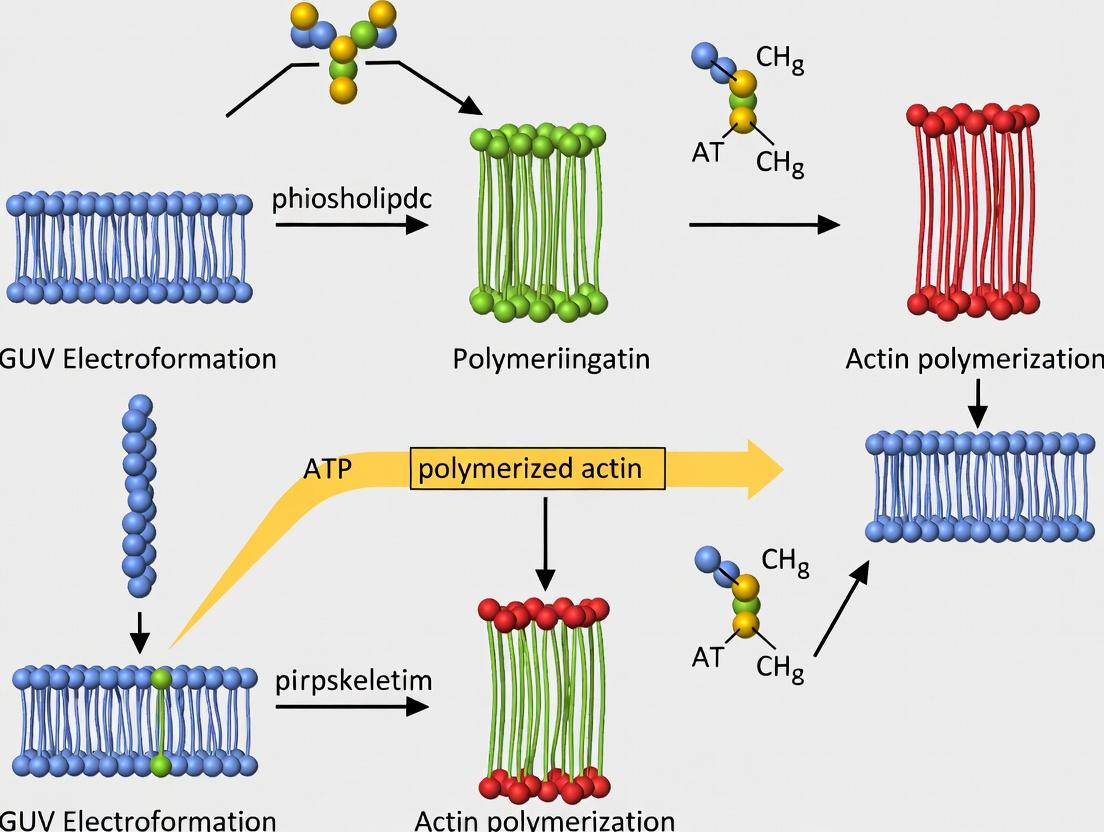
Experimental Workflow for Integrated Actin Polymerization Assay
Diagram Title: Integrated GUV Electroformation and Actin Assay Workflow
Key Signaling Pathway for Actin Nucleation on PIP₂-Containing GUVs
Diagram Title: PIP2-Mediated Actin Nucleation at GUV Membrane
Application Notes on Cytoskeletal Regulation in GUV Models
The actin cytoskeleton provides mechanical support, enables cell motility, and facilitates intracellular transport. In the context of Giant Unilamellar Vesicle (GUV) electroformation research, reconstituting actin dynamics within a defined membrane system allows for the study of fundamental processes like membrane protrusion, endocytosis, and the mechanical coupling between the cortex and the membrane. This is critical for modeling cell behavior and for drug screening targeting cytoskeletal pathologies (e.g., cancer metastasis, immunodeficiencies).
Key Regulatory Nodes:
- ARP2/3 Complex: Nucleates new actin filaments as branches on existing "mother" filaments, creating dendritic networks essential for lamellipodial protrusion. In GUVs, it is used to generate a branched cortical network.
- Capping Protein (e.g., CapZ): Binds to the fast-growing barbed ends of actin filaments, preventing further subunit addition/removal. It sharpens the spatial control of network growth by promoting nucleation of new filaments over elongation of old ones.
- Formins (e.g., mDia1): Processively nucleate and elongate unbranched, linear actin filaments. They remain attached to the barbed end, protecting it from capping protein, and are crucial for filopodia formation and contractile ring assembly.
Quantitative Parameters of Key Actin Regulators
Table 1: Kinetic and Binding Parameters of Core Actin Regulatory Proteins
| Protein | Primary Function | Key Parameter | Typical Value / Range | Experimental Context |
|---|---|---|---|---|
| Actin (G-actin) | Polymerization Subunit | Critical Concentration (Cc) | ~0.1 µM (barbed end)~0.6 µM (pointed end) | Pyrene-actin polymerization assay |
| ARP2/3 Complex | Branch Nucleation | Branch Frequency | 1 branch / ~1000 subunits (<5 µM ARP2/3) | TIRF microscopy of actin networks |
| Activation (by VCA/N-WASP) | Kd ~0.1 - 1.0 µM | Surface Plasmon Resonance | ||
| Capping Protein | Barbed End Capping | Binding Affinity (Kd) | ~0.1 - 1.0 nM | Fluorescence anisotropy |
| On-rate (k_on) | ~5 - 10 µM⁻¹s⁻¹ | Stopped-flow kinetics | ||
| Formin (mDia1) | Processive Elongation | Elongation Rate | 5 - 50 subunits/s (at 1 µM actin) | TIRF microscopy, single-filament analysis |
| Processivity | Can remain bound for 1000s of subunits |
Table 2: Typical Concentrations for In Vitro Reconstitution in GUV Experiments
| Component | Functional Role in GUV Assay | Recommended Starting Concentration | Notes |
|---|---|---|---|
| G-Actin (with e.g., 10% labeled) | Filament backbone | 1 - 4 µM | Lower conc. for slower, more controllable growth. |
| ARP2/3 Complex | Generate branched network | 5 - 50 nM | Titrate to control branch density. Requires activator (VCA). |
| Capping Protein | Limit filament length, control network density | 1 - 10 nM | Powerful regulator; use at low nanomolar concentrations. |
| Formin (FH1FH2) | Generate linear, bundled filaments | 1 - 10 nM | Often tethered to GUV membrane via a lipid anchor. |
| N-WASP VCA domain | Activate ARP2/3 complex | 10 - 100 nM | Can be soluble or membrane-tethered. |
| Profilin | Enhance formin-mediated elongation | 1 - 5 µM | Supplies ATP-actin to formin-bound barbed ends. |
Detailed Experimental Protocols
Protocol 1: Electroformation of GUVs for Actin Reconstitution
Aim: To produce giant unilamellar vesicles (GUVs) >10 µm in diameter with a defined lipid composition suitable for subsequent encapsulation or external attachment of actin regulatory components.
Materials:
- Lipids: DOPC, DOPS, Biotinyl-Cap-PE, cholesterol (e.g., 65:20:5:10 molar ratio).
- Solvent: Chloroform.
- Electroformation Chamber: Indium tin oxide (ITO)-coated glass slides, silicone spacer.
- Sucrose/Glucose Solutions: 200 mM sucrose (inner solution), 200 mM glucose (outer solution, osmotically matched).
- AC Function Generator.
Procedure:
- Clean ITO slides thoroughly with ethanol and Milli-Q water.
- Prepare a 2 mM lipid stock in chloroform. Spot 10-20 µL onto one ITO slide and dry under vacuum for ≥2 hours to remove all solvent.
- Assemble the chamber with the lipid-coated slide, a silicone gasket (1-2 mm thick), and the second ITO slide.
- Fill the chamber with the inner sucrose solution (200 mM sucrose, optionally containing chelators like EGTA).
- Connect the slides to the AC generator. Apply a sinusoidal AC field (1.0 V, 10 Hz) for 1-2 hours at 60-65°C (above lipid Tm).
- Gradually lower the frequency to 2-4 Hz over 30 minutes. GUVs will form and detach into the solution.
- Carefully harvest GUVs from the chamber using a syringe. Keep on ice.
- Prior to experiments, gently mix GUV suspension 1:1 with an outer glucose solution (200 mM) containing actin monomers and regulatory proteins. The density difference will settle GUVs for microscopy.
Protocol 2: TIRF Microscopy Assay for Actin Network Growth on GUVs
Aim: To visualize the spatiotemporal dynamics of actin polymerization nucleated by membrane-tethered factors on GUVs.
Materials:
- Flow Chamber: Passivated glass coverslip coated with PEG and biotin-PEG.
- Streptavidin: 0.2 mg/mL in PBS.
- Biotinylated GUVs: From Protocol 1.
- TIRF Microscope: With 488 nm and 561 nm lasers, EMCCD or sCMOS camera.
- Polymerization Mix (in G-Buffer + 1 mM Mg-ATP): 1 µM G-actin (10% Alexa-488 labeled), 50 nM profilin, 100 nM VCA (if using ARP2/3), 50 nM ARP2/3 complex, 2 nM capping protein, oxygen scavenger system (glucose oxidase/catalase), and Trolox.
Procedure:
- Prepare the imaging chamber: Inject streptavidin into a passivated flow cell, incubate 2 min, wash with buffer. This creates a surface to immobilize biotinylated GUVs.
- Immobilize GUVs: Dilute biotinylated GUVs in glucose buffer and inject into the chamber. Allow to settle and bind to the surface for 5-10 min. Wash with glucose buffer.
- Initiate Polymerization: Gently inject the Polymerization Mix. Start imaging immediately.
- Image Acquisition: Use TIRF illumination to excite fluorophores within ~100 nm of the coverslip, capturing the base of the GUV. Acquire frames every 5-10 seconds for 10-20 minutes.
- Analysis: Use software (Fiji, TrackMate, etc.) to quantify network growth rate, filament density, and branching frequency.
Diagrams of Pathways and Workflows
The Scientist's Toolkit: Research Reagent Solutions
Table 3: Essential Reagents for GUV-Based Actin Polymerization Research
| Reagent / Material | Supplier Examples | Key Function in Experiment |
|---|---|---|
| Purified Muscle or Non-Muscle Actin | Cytoskeleton Inc., Hypermol | Core polymeric protein. Often pre-labeled with fluorophores (e.g., Alexa-488, -568) for visualization. |
| Recombinant Human ARP2/3 Complex | Cytoskeleton Inc., homemade expression | The central branching nucleator. Requires an activator (VCA/WASP) for function. |
| Recombinant Capping Protein (CapZ) | MyBioSource, homemade expression | Controls filament length and network architecture by blocking barbed end dynamics. |
| Recombinant Formin (FH1FH2 domains) | Sino Biological, homemade expression | Nucleates and processively elongates linear, unbranched filaments. |
| Profilin | Cytoskeleton Inc. | Binds G-actin, promotes exchange of ADP for ATP, and delivers actin to formin-bound ends. |
| Lipids (DOPC, DOPS, Biotinyl-Cap-PE) | Avanti Polar Lipids | Building blocks for GUV membrane with controlled charge and functionalization for tethering. |
| TIRF Microscope System | Nikon, Olympus, Zeiss | Enables high-contrast, high-resolution imaging of fluorescent actin structures near the GUV membrane. |
| Oxygen Scavenging System | Sigma-Aldrich (Glucose Oxidase, Catalase) | Reduces photobleaching and fluorophore blinking during long time-lapse imaging. |
Application Notes
This document details protocols for mimicking the mechanics of the cellular actin cortex using Giant Unilamellar Vesicles (GUVs) in a controlled, cell-free environment. This approach, framed within broader GUV electroformation actin polymerization research, provides a minimal system to dissect the physical and biochemical principles governing cortical tension, stability, and its response to biochemical effectors. This platform is critical for researchers and drug development professionals aiming to understand cytoskeletal mechanics and screen compounds that modulate cortical integrity.
Core Principles & Quantitative Data Summary: The cellular cortex is a thin, dynamic network of actin filaments and myosin motors beneath the plasma membrane. Mimicking it requires the co-reconstitution of these components on a lipid bilayer. Key quantitative parameters from recent literature (2023-2024) for successful reconstitution are summarized below.
Table 1: Key Quantitative Parameters for Cortex Mimicry on GUVs
| Parameter | Typical Target Range | Function & Rationale |
|---|---|---|
| GUV Diameter | 10 - 50 µm | Optimal for microscopy and analogous to cell size. |
| Lipid Composition (PC:PS) | 80:20 to 70:30 mol% | PC provides bilayer integrity; PS recruits actin-binding proteins via electrostatic interactions. |
| Actin Concentration | 1 - 4 µM (0.1 - 0.5 mg/mL) | Sufficient for network formation without excessive internal polymerization. |
| Actin:N-WASP/Arp2/3 Ratio | 10:1 to 50:1 (actin:N-WASP) | Promotes branched network formation characteristic of the cortex. |
| Myosin II (HMM) Concentration | 10 - 100 nM | Induces contractility and network tension. |
| Ionic Strength Buffer | 50 - 100 mM KCl, 1 mM MgCl₂ | Balances protein activity and membrane stability. |
| ATP Concentration | 1 - 2 mM | Fuels actin polymerization and myosin motor activity. |
| Electroformation Voltage (AC) | 1 - 2 V (peak-to-peak), 10 Hz | Standard for gentle GUV formation from dried lipid films. |
Table 2: Key Measurable Outputs & Their Implications
| Output Measurement | Technique | Target/Healthy Mimic | Significance for Drug Screening |
|---|---|---|---|
| Cortex Thickness | TIRF/Confocal microscopy | 0.2 - 0.5 µm | Indicator of proper network density and organization. |
| Cortical Tension | Micropipette Aspiration/Flicker Spectroscopy | 0.01 - 0.05 mN/m | Direct readout of mechanical stability. Decreased by disruptors. |
| Network Viscoelasticity (G') | Optical Tweezers/Bead Rheology | G' > 1 Pa (elastic-dominated) | Measures structural integrity. Compounds altering cross-linking alter G'. |
| Contraction Rate | Time-lapse microscopy | 0.1 - 0.5 %/s area decrease (with myosin) | Reports on myosin activity and actomyosin regulation. |
Experimental Protocols
Protocol 1: GUV Electroformation with Phosphatidylserine
Objective: To produce PS-containing GUVs for subsequent protein recruitment. Materials: 1,2-dioleoyl--sn-glycero-3-phosphocholine (DOPC), 1,2-dioleoyl--sn-glycero-3-phospho-L-serine (DOPS), Chloroform, Indium Tin Oxide (ITO)-coated glass slides, Electroformation chamber, Function generator.
- Prepare a 2 mg/mL lipid stock in chloroform at a DOPC:DOPS molar ratio of 80:20.
- Deposit 20 µL of lipid solution onto one conductive side of an ITO slide. Spread evenly and dry under vacuum for 60 minutes to form a thin lipid film.
- Assemble the electroformation chamber using the lipid-coated slide, a spacer, and a second ITO slide.
- Fill the chamber with a 200-300 mOsm sucrose solution (provides osmotic balance for later steps).
- Connect the chamber to a function generator. Apply an AC field: 1.2 V (peak-to-peak) at 10 Hz for 90 minutes at 37°C, followed by 2 Hz for 30 minutes.
- Carefully harvest GUVs from the chamber using a blunt syringe.
Protocol 2: Reconstitution of an Actomyosin Cortex on GUVs
Objective: To form a contractile actin network on the inner leaflet of GUVs. Materials: GUVs (from Protocol 1), G-Actin (from rabbit muscle, lyophilized), Arp2/3 complex, N-WASP, Myosin II (HMM), ATP, Gel-Filtration Buffer (50 mM KCl, 1 mM MgCl₂, 1 mM EGTA, 10 mM Imidazole pH 7.4), Glucose/Oxidase/Catalase mix for oxygen scavenging.
- Actin Polymerization Mix: Thaw and clarify G-actin by gel filtration. Prepare a polymerization mix on ice: 2 µM G-actin, 50 nM N-WASP, 20 nM Arp2/3 complex, 100 nM Myosin II (HMM), 2 mM ATP, oxygen scavenging system (25 mM glucose, 100 µg/mL glucose oxidase, 20 µg/mL catalase) in gel-filtration buffer.
- GUV Transfer: Sediment harvested GUVs (in sucrose) by gentle centrifugation (500 x g, 5 min). Resuspend the GUV pellet in an equal volume of an isosmotic glucose solution. This creates a density difference (sucrose inside GUVs, glucose outside) that stabilizes vesicles for imaging.
- Cortex Assembly: Mix 10 µL of the actin polymerization mix with 10 µL of the glucose-resuspended GUVs in a glass-bottom imaging chamber. Incubate for 15-20 minutes at room temperature to allow actin nucleation, polymerization, and attachment to the PS-containing membrane via N-WASP/Arp2/3.
- Imaging: Image immediately using confocal or TIRF microscopy (e.g., label actin with Alexa Fluor 488 phalloidin post-assembly or use trace amounts of labeled G-actin).
Protocol 3: Quantifying Cortical Tension via Flicker Spectroscopy
Objective: To non-invasively measure the tension of the GUV-bound actin cortex. Materials: Prepared GUVs (from Protocol 2), High-speed camera on phase-contrast or fluorescence microscope, Analysis software (e.g., custom MATLAB/Python scripts).
- Acquire a high-temporal-resolution video (>100 fps) of an uncontracted, cortex-coated GUV.
- For each frame, extract the vesicle contour using edge-detection algorithms.
- Perform a spherical harmonics decomposition on the contour fluctuations.
- Analyze the mean squared amplitude of fluctuation modes as a function of wave number. Fit to the thermal fluctuation spectrum of a tense membrane.
- The fit yields the cortical tension (σ). Compare values for GUVs with actin-only vs. actin+myosin cortices.
Visualizations
Title: GUV Cortex Reconstitution Workflow
Title: Minimal Signaling for Synthetic Cortex Mechanics
The Scientist's Toolkit
Table 3: Key Research Reagent Solutions
| Item | Function in Experiment | Critical Notes |
|---|---|---|
| DOPC & DOPS Lipids | Form the foundational phospholipid bilayer. PS provides negative charge for protein recruitment. | Use high-purity (>99%), store in inert atmosphere. |
| Sucrose/Glucose Osmotic Pair | Creates density difference to stabilize GUVs for imaging; provides osmotic support. | Match osmolarities precisely (±10 mOsm) to prevent vesicle rupture. |
| G-Actin (Lyophilized) | Monomeric actin, the building block of the cortical network. | Always clarify by gel filtration before use to remove aggregates. |
| Arp2/3 Complex | Key nucleator that creates branched actin networks, mimicking cortical architecture. | Activity between batches can vary; titrate for optimal branching density. |
| N-WASP (VCA domain) | Activates Arp2/3 complex; links membrane (via PS) to the actin polymerization machinery. | A minimal VCA domain fragment is often sufficient for reconstitution. |
| Myosin II (HMM) | Dimeric motor protein that induces cross-linking and contraction in the actin network. | Ensure it is biochemically active; test via motility assay. |
| ATP Regeneration System | Maintains constant ATP levels during long experiments; prevents depletion. | Typically includes creatine phosphate and creatine kinase. |
| Oxygen Scavengers | Reduces photodamage during fluorescence imaging by removing reactive oxygen species. | Glucose oxidase/catalase system is most common. |
Within the broader thesis on reconstructing the actin cytoskeleton inside Giant Unilamellar Vesicles (GUVs) via electroformation and subsequent polymerization, the reproducibility and physiological relevance of experiments hinge on three foundational pillars: the selection of lipids to mimic target membranes, the formulation of buffers to maintain protein stability and function, and the purification of high-quality, polymerization-competent actin. These components are interdependent; suboptimal choices in one can invalidate the entire reconstitution. This application note details protocols and quantitative comparisons to establish robust methodologies for advancing GUV-based cytoskeletal research.
Lipid Choices for Electroformation
The lipid composition defines GUV physical properties (fluidity, charge, curvature) and biochemical functionality (protein recruitment, signaling).
Key Considerations:
- Charge: Phosphatidylserine (PS) recruits proteins via electrostatic interactions.
- Headgroup Function: Phosphatidylinositol (4,5)-bisphosphate (PIP₂) is critical for nucleating actin via N-WASP/Arp2/3.
- Phase State: A mixture of DOPC (fluid, unsaturated) and DPPC (gel-phase, saturated) can create lipid domains.
- Fluorescent Labeling: A small fraction (0.1-0.5 mol%) of headgroup-labeled lipids (e.g., Texas Red-DHPE) enables visualization.
Table 1: Common Lipids for Actin-Reconstitution GUVs
| Lipid Name | Abbreviation | Mol% (Example) | Function in Actin Research | Phase State (at 25°C) |
|---|---|---|---|---|
| 1,2-dioleoyl-sn-glycero-3-phosphocholine | DOPC | 55-80 | Neutral matrix lipid, high fluidity | Liquid-disordered (Ld) |
| 1,2-dioleoyl-sn-glycero-3-phospho-L-serine | DOPS | 15-20 | Introduces negative charge, recruits proteins | Ld |
| Cholesterol | Chol | 0-30 | Modulates membrane fluidity & stiffness | - |
| L-α-phosphatidylinositol (4,5)-bisphosphate | PIP₂ | 0.5-2 | Key signaling lipid, nucleates actin networks | Ld |
| 1,2-dipalmitoyl-sn-glycero-3-phosphocholine | DPPC | 0-20 | Can induce phase separation for domain studies | Solid-ordered (So) |
Protocol: Lipid Mixture Preparation for Electroformation
- Calculate & Combine: Using mol% targets, calculate volumes from stock solutions (typically 10-25 mg/mL in chloroform). Combine lipids in a glass vial.
- Add Tracer: Include 0.2 mol% of a fluorescent lipid (e.g., Atto 488-DOPE) for microscopy.
- Dry Thin Film: Under a gentle stream of argon or nitrogen, evaporate the chloroform to form a thin lipid film on the vial wall. Then, place under vacuum for >2 hours to remove trace solvent.
- Rehydrate for Electroformation: Rehydrate the film with the desired internal (sucrose) buffer at ~60°C for 30 minutes to a final lipid concentration of 0.5-1 mM. Vortex gently to create a multilamellar suspension.
- Assemble Chamber: Place the lipid suspension between two Indium Tin Oxide (ITO)-coated glass slides separated by a 2-3 mm gasket. Apply an AC electric field (1-10 Hz, 0.5-2 V) for 1-2 hours at a temperature above the lipid mixture's transition temperature (e.g., 55°C for DOPC/DPPC mixtures).
- Harvest GUVs: Carefully disassemble the chamber and collect the GUV solution. Store at 4°C and use within 48 hours.
Buffer Composition for Actin Dynamics
Buffers must support both GUV integrity and the ionic/chemical environment for actin polymerization.
Table 2: Critical Buffer Components for Actin Polymerization
| Component | Typical Concentration | Function | Critical Consideration |
|---|---|---|---|
| Tris-HCl or HEPES | 5-50 mM, pH 7.0-7.5 | pH buffering | HEPES is preferred for fluorescence microscopy. |
| KCl | 50-150 mM | Ionic strength for actin polymerization | Too low (<50 mM) reduces polymerization rate; too high can affect GUV stability. |
| MgCl₂ | 1-2 mM | Essential cofactor for ATP-actin | Required for stable F-actin. |
| ATP | 0.2-2 mM | Energy source for actin monomer turnover | Must be fresh; include an ATP-regeneration system for long experiments. |
| DTT or TCEP | 0.5-1 mM | Reducing agent, prevents actin cysteine oxidation | Essential for maintaining monomer functionality. |
| CaCl₂/EGTA or EDTA | 0.1 mM Ca²⁺ / 0.2 mM EGTA | Controls divalent cation availability | Actin is typically stored as Ca²⁺-ATP-actin; polymerization is initiated by switching to Mg²⁺-ATP-actin. |
| Sucrose/Glucose (Osmolyte) | 100-400 mOsm inside GUVs | Creates osmotic balance to stabilize GUVs | Internal (sucrose) and external (glucose) isosmolar solutions enable phase-contrast imaging. |
Protocol: G-Compatible Buffer (GB) for Inside-GUV Actin Assembly
- Internal Buffer (Sucrose-based): 50 mM HEPES (pH 7.5), 50 mM KCl, 1 mM MgCl₂, 1 mM ATP, 1 mM DTT, 0.2 mM EGTA, 200 mM sucrose.
- External Buffer (Glucose-based): 50 mM HEPES (pH 7.5), 50 mM KCl, 1 mM MgCl₂, 1 mM ATP, 1 mM DTT, 0.2 mM EGTA, 200 mM glucose.
- Preparation: Adjust pH of both buffers to 7.5 at room temperature. Filter sterilize (0.22 µm). Osmolarity should be matched (±5%) using an osmometer.
Actin Purification from Muscle Acetone Powder
High-purity, polymerization-competent monomeric actin (G-actin) is non-negotiable.
Protocol: Rabbit Skeletal Muscle Actin Purification (Modified from Spudich & Watt)
- Day 1: Extraction & Polymerization.
- Extract 5g acetone powder with 100 mL cold G-buffer (2 mM Tris-HCl pH 8.0, 0.2 mM CaCl₂, 0.2 mM ATP, 0.5 mM DTT) for 30 min on ice with stirring.
- Centrifuge at 15,000 x g for 30 min at 4°C. Filter supernatant through glass wool.
- Add KCl to 50 mM and MgCl₂ to 2 mM to induce polymerization. Incubate for 1.5-2 hours at room temperature.
- Day 2: Depolymerization & Polymerization Cycles.
- Add solid KCl to 0.8 M and stir for 30 min to "salt-out" tropomyosin/troponin.
- Ultracentrifuge at 150,000 x g for 3 hours at 4°C to pellet F-actin.
- Resuspend pellet in cold G-buffer + 0.2 mM CaCl₂ using a Dounce homogenizer. Dialyze against 1 L of the same buffer for 48-72 hours at 4°C to depolymerize actin.
- Clarify by ultracentrifugation at 150,000 x g for 2 hours. The supernatant is G-actin.
- Final Steps: Determine concentration (A290, ε = 26,600 M⁻¹cm⁻¹). Snap-freeze in liquid nitrogen in small aliquots and store at -80°C. For experiments, thaw rapidly and clear by ultracentrifugation (100,000 x g, 1 hour) immediately before use.
Table 3: Quality Control Metrics for Purified Actin
| Parameter | Target Value | Assessment Method |
|---|---|---|
| Concentration | >40 µM (after clarification) | UV absorbance at 290 nm |
| Purity (Actin Band) | >95% | SDS-PAGE (Coomassie staining) |
| Polymerization Competence | T₁/₂ < 5 min | Pyrene-actin fluorescence assay |
| Monomeric State (Post-Thaw) | >99% | Analytical ultracentrifugation or gel filtration |
The Scientist's Toolkit: Research Reagent Solutions
| Item | Function in GUV/Actin Research | Key Example/Note |
|---|---|---|
| Lipids (Avanti Polar Lipids) | High-purity, defined synthetic lipids for reproducible membrane composition. | DOPS (840035), PIP₂ (840046) |
| Indium Tin Oxide (ITO) Slides | Conductive, transparent electrodes for electroformation chamber. | RMS supplies, 8-12 Ω/sq resistance. |
| ATP-Regeneration System | Maintains constant [ATP] for prolonged actin dynamics. | Creatine phosphate (20 mM) + Creatine Kinase (10 U/mL). |
| Pyrene Iodoacetamide | Fluorescent probe for labeling actin Cys-374 to monitor polymerization kinetics. | Use at a 1:10 label:actin ratio. |
| Sephacryl S-300 HR | Size-exclusion chromatography resin for final actin monomer purification. | Removes small aggregates. |
| Gel Filtration Buffer | Storage buffer for actin post-thaw clarification. | 2 mM Tris-HCl pH 8.0, 0.2 mM CaCl₂, 0.2 mM ATP, 0.5 mM DTT, 0.01% NaN₃. |
Visualizations
Diagram 1: Integrated GUV Actin Reconstitution Workflow (82 characters)
Diagram 2: PIP₂-Mediated Actin Nucleation Pathway (62 characters)
Application Notes
Bottom-up reconstitution within Giant Unilamellar Vesicles (GUVs) represents a frontier in synthetic biology and biophysical research. By assembling minimal cellular components—membranes, cytoskeletal networks, and reaction circuits—inside GUVs, we create controllable model systems to dissect the fundamental principles of life. This approach is central to a thesis investigating actin polymerization dynamics within a confined, cell-like environment established via electroformation. These synthetic cells serve as ideal test beds for probing the physical rules governing cytoskeletal self-organization, membrane-cytoskeleton coupling, and the emergence of morphogenesis. For drug development, such systems enable the high-throughput screening of compounds targeting cytoskeletal dynamics (e.g., anti-cancer agents) in a reductionist context, free from the complexity of whole cells.
Recent advances highlight the integration of active cytoskeletal networks with adhesion motifs or lipid domains to mimic cell spreading and mechanosensing. Furthermore, the incorporation of light-inducible or chemically inducible signaling pathways allows for spatiotemporal control over actin nucleation, enabling precise tests of network theories. Data from such experiments are quantifying the feedback between membrane tension, curvature, and actin growth.
Table 1: Quantitative Parameters from Recent GUV-Actin Reconstitution Studies
| Parameter | Typical Range / Value | Significance | Measurement Technique |
|---|---|---|---|
| GUV Diameter | 10 - 100 µm | Provides confinement geometry; affects network scaling. | Fluorescence microscopy, phase contrast. |
| Actin Filament Length (in confinement) | 0.5 - 20 µm | Determines network mesh size and mechanical properties. | TIRF/confocal microscopy after phalloidin staining. |
| Critical Concentration (Cc) of Actin | ~0.1 µM (ATP-actin) | Baseline for polymerization; altered by crowding & confinement. | Pyrene-actin fluorescence assay. |
| Actin Polymerization Rate (V+) | 1 - 10 subunits/s/µM | Dictates speed of network assembly and force generation. | TIRF microscopy of single filaments. |
| Arp2/3 Branching Angle | 70° ± 7° | Defines network architecture (dendritic vs. bundled). | Electron microscopy, angular analysis in reconstituted networks. |
| Membrane Tension during Actin Comet Formation | 0.01 - 0.1 mN/m | Coupling parameter; actin growth can reduce local tension. | Fluctuation analysis or micropipette aspiration. |
Protocols
Protocol 1: Electroformation of Neutral GUVs for Actin Reconstitution
Objective: To produce charge-neutral, defect-free GUVs in an iso-osmotic sucrose solution suitable for subsequent injection of actin polymerization mixtures.
Materials:
- Research Reagent Solutions:
- 1,2-dioleoyl-sn-glycero-3-phosphocholine (DOPC): Primary neutral lipid for forming the fluid bilayer.
- Cholesterol: Modulates membrane fluidity and stability.
- Chloroform: Solvent for lipid stock solutions.
- Indium Tin Oxide (ITO)-coated glass slides: Conductive substrates for applying the AC field.
- Sucrose solution (300 mOsm/kg): Inner solution for vesicle formation; provides density for subsequent manipulation.
- Glucose solution (300 mOsm/kg): Outer solution; osmolarity matching creates an index gradient for microscopy.
- AC Power Supply/Function Generator: Provides the oscillating electric field for gentle vesicle growth.
Method:
- Lipid Film Preparation: Mix DOPC and cholesterol (9:1 molar ratio) in chloroform to a total lipid concentration of 2 mM. Pipette 20-30 µL of this solution onto the conductive side of a clean ITO slide. Spread evenly.
- Solvent Evaporation: Place the slide in a desiccator under vacuum for ≥2 hours to remove all traces of chloroform, forming a dry lipid film.
- Electroformation Chamber Assembly: Assemble a chamber by placing a silicone O-ring (~1-2 mm thick) on the lipid-coated slide. Fill the well with 300 µL of the 300 mOsm/kg sucrose solution. Carefully place a second ITO slide on top, conductive side down, to seal the chamber.
- Vesicle Growth: Connect the slides to the function generator. Apply a sinusoidal AC field (10 Hz, 1.1 Vpp for 10 minutes, then 2 Hz, 1.1 Vpp for 90-120 minutes) at room temperature.
- Harvesting: Gently disassemble the chamber. Collect the vesicle-containing sucrose solution using a cut pipette tip to avoid shear stress. Store at 4°C for up to 48 hours.
Protocol 2: Microinjection of Actin Nucleation Machinery into GUVs
Objective: To encapsulate purified actin (monomeric, G-actin), nucleation-promoting factors (e.g., WASP-VCA domain), and the Arp2/3 complex inside pre-formed GUVs to initiate controlled dendritic network assembly.
Materials:
- Research Reagent Solutions:
- Monomeric Actin (G-actin), labeled & unlabeled: The building block for filaments. Fluorescent label (e.g., Alexa Fluor 488) allows visualization.
- Arp2/3 Complex: Nucleates new filaments as branches from existing ones.
- N-WASP VCA Domain: Activates Arp2/3 complex, linking it to signaling inputs.
- EGTA: Chelates Mg2+ to maintain G-actin in monomeric state during loading.
- 10x Polymerization Buffer (1x: 50 mM KCl, 1 mM MgCl2, 1 mM ATP, 10 mM Tris, pH 7.5): Initiates actin polymerization upon injection and dilution.
Method:
- Sample Preparation: Prepare the "injection mix" containing 4 µM G-actin (10% labeled), 50 nM Arp2/3 complex, 100 nM VCA, and 0.2 mM EGTA in a low-ionic-strength buffer (e.g., 5 mM Tris, pH 7.5).
- GUV Preparation: Prepare a microscopy chamber with the glucose solution (outer solution). Add harvested GUVs (in sucrose) to the chamber. The density difference causes GUVs to settle onto the coverslip.
- Microinjection Setup: Load the injection mix into a microinjection needle. Using a micromanipulator and an inverted epifluorescence/confocal microscope, position the needle near a settled GUV.
- Injection: Gently pierce the GUV membrane and inject a small volume (~1-5% of GUV volume) using a controlled pressure pulse (Pico-injector or manual system).
- Polymerization Initiation: The injected components diffuse within the GUV. Polymerization is triggered intrinsically as the mix encounters the Mg2+ present in the GUV's sucrose interior (from buffers) or can be enhanced by diffusional exchange with the outer glucose solution containing 1x polymerization buffer. Image immediately using time-lapse microscopy.
Diagram 1: GUV electroformation and actin injection workflow
Diagram 2: Minimal actin polymerization signaling pathway
Step-by-Step Protocol: From Electroformation to Actin Assembly Inside GUVs
This protocol is the foundational methodology for a broader thesis investigating the dynamics of actin polymerization inside Giant Unilamellar Vesicles (GUVs). The production of high-yield, defect-free GUVs via electroformation is critical for creating biomimetic compartments that serve as minimal cell models. Subsequent protocols will utilize these GUVs as synthetic cytoplasms to study actin network assembly under confinement, relevant for understanding cell mechanics and for drug development targeting the cytoskeleton.
Optimized Electroformation Protocol
Materials & Reagent Solutions
The Scientist's Toolkit: Essential Materials for GUV Electroformation
| Item | Function/Brief Explanation |
|---|---|
| Indium Tin Oxide (ITO) coated glass slides | Conductive, transparent substrates for applying the electric field during vesicle formation. |
| Lipid stock solutions (e.g., DOPC, DOPS, cholesterol) | Dissolved in chloroform or chloroform/methanol mixtures. Form the structural basis of the bilayer. DOPC is common for neutral membranes; DOPS introduces negative charge. |
| Electroformation chamber | Custom-built or commercial chamber to hold ITO slides, seal in sucrose solution, and connect to a function generator. |
| Low-frequency function generator | Provides the AC field (sinusoidal waveform) critical for gentle lipid swelling and vesicle detachment. Must offer precise control over frequency and voltage. |
| Sucrose solution (200-500 mM) | The internal solution for lipid swelling. The osmolarity is typically matched later with an external glucose solution to facilitate imaging and sedimentation. |
| Glucose solution (equiosmolar to sucrose) | External solution used for harvesting. Density difference (sucrose inside/glucose outside) aids in GUV settling and improves optical contrast. |
| Temperature-controlled environment | Oven or hot plate. Elevated temperature (often above the lipid phase transition temperature, e.g., 37-45°C for DOPC) is required during electroformation. |
| Vacuum desiccator | Used to thoroughly dry the lipid film on the ITO slide, removing all traces of organic solvent. |
Detailed Step-by-Step Methodology
Day 1: Slide Preparation and Lipid Deposition
- Clean ITO slides: Sonicate slides in 2% Hellmanex III solution, rinse extensively with Milli-Q water, and dry with nitrogen stream.
- Prepare lipid mixture: In a glass vial, combine lipids from stock solutions to achieve desired molar composition (e.g., 80:20 DOPC:DOPS). Evaporate solvent under a gentle nitrogen stream.
- Redissolve lipids: Add a small volume of chloroform (e.g., 50 µL) to achieve a final lipid concentration of 0.2-1.0 mg/mL.
- Deposit lipid film: Using a Hamilton syringe, spread 20-30 µL of the lipid solution evenly onto the conductive side of an ITO slide.
- Desiccate: Immediately place the slide in a vacuum desiccator for a minimum of 2 hours to remove all organic solvent, forming a dry lipid film.
Day 2: Electroformation and Harvesting
- Assemble chamber: Assemble the electroformation chamber using the lipid-coated slide and a clean spacer/slide. Seal with silicone grease.
- Fill with sucrose: Inject the chamber with the pre-warmed sucrose solution (e.g., 200 mM) using a syringe, ensuring no air bubbles are trapped.
- Connect to generator: Attach electrodes from the function generator to the ITO slides' conductive contacts.
- Apply AC field: Place the chamber in a temperature-controlled environment (e.g., 37°C oven). Apply the AC field using the optimized parameters from Table 1.
- Monitor growth: Over 1-2 hours, vesicles should become visible under a microscope. Allow growth to continue for the full duration.
- Harvest GUVs: Carefully disassemble the chamber. Gently flush the GUV-containing sucrose solution into a collection vial using an equiosmolar glucose solution. This exchange creates a density gradient.
Optimized Electroformation Parameters
Based on current literature and experimental validation for neutral and slightly charged lipid mixtures, the following parameters yield high concentrations of large, unilamellar GUVs suitable for actin polymerization studies.
Table 1: Optimized AC Electroformation Parameters
| Lipid Composition | AC Frequency | Voltage (Peak-to-Peak) | Duration | Temperature | Key Outcome |
|---|---|---|---|---|---|
| Pure DOPC (neutral) | 10 Hz | 1.0 V | 90-120 min | 37 °C | High yield of large (10-50 µm) vesicles, low defect frequency. |
| DOPC/DOPS (80:20 mol%) | 5 Hz | 1.2 V | 120 min | 37 °C | Stable charged vesicles. Slightly lower frequency compensates for charge. |
| DOPC/Cholesterol (70:30 mol%) | 10 Hz | 1.5 V | 150 min | 45 °C | Increased rigidity. Higher voltage and temperature aid swelling. |
| DOPC/Brain PI(4,5)P₂ (98:2 mol%) | 8 Hz | 1.0 V | 90 min | 37 °C | For signaling studies. Minimal voltage to avoid lipid degradation. |
Note: All parameters assume a sinusoidal waveform. Voltages are applied across a typical chamber gap of 2-3 mm.
Visualization of Experimental Workflow
Title: GUV Electroformation and Downstream Use Workflow
Integration into Actin Polymerization Research
The harvested GUVs, containing an internal sucrose solution, are incubated with actin monomers (G-actin), polymerization salts (Mg²⁺, KCl), and energy-regeneration systems. The external glucose solution provides osmotic balance and contrast. Polymerization can be initiated inside the GUVs via specific triggers (e.g., adding actin nucleators or releasing caged compounds), and the resulting filament network dynamics are observed via fluorescence microscopy (using rhodamine- or Alexa-labeled actin).
Signaling Pathway for Actin Assembly Inside GUVs
Title: Actin Polymerization Pathway in GUV Confinement
Application Notes
Within the broader thesis on reconstructing the actin cytoskeleton inside Giant Unilamellar Vesicles (GUVs) via electroformation, the efficient and controlled encapsulation of actin monomers (G-actin) and regulatory proteins (e.g., profilin, Arp2/3 complex, capping protein) is a critical bottleneck. This protocol details strategies to overcome this challenge, moving beyond passive encapsulation to achieve physiologically relevant, active cytoskeletal assemblies. Successful encapsulation is defined by three parameters: final intra-GUV concentration, encapsulation efficiency (% of initial material encapsulated), and protein functionality post-encapsulation. The choice of strategy depends on the specific regulatory network under investigation and the required spatial and temporal control over polymerization.
Data Presentation: Encapsulation Method Comparison
Table 1: Comparison of Core Actin/Protein Encapsulation Strategies for GUVs
| Method | Principle | Typical Encapsulation Efficiency (Proteins) | Key Advantages | Key Limitations | Best For |
|---|---|---|---|---|---|
| Passive Encapsulation | Proteins are present in the aqueous buffer during GUV electroformation. | 0.1 - 2% | Simple; no specialized equipment; co-encapsulation of multiple components. | Very low efficiency; uncontrolled concentration; large sample waste. | Initial proof-of-concept for simple actin polymerization. |
| Modified Electroformation (Sucrose/Glucose Shift) | Electroformation is performed in a high-density sucrose solution. Post-formation, the external solution is exchanged for isotonic glucose, creating an osmotic gradient that preferentially retains denser contents. | 5 - 15% | Moderate improvement in efficiency; uses standard electroformation setup. | Efficiency varies with vesicle size; can cause vesicle deformation. | Improved yield for defined protein mixtures. |
| Continuous Droplet Transfer | A water-in-oil droplet containing the proteins is transferred across an oil-water interface to become a GUV. | 20 - 60% | High and tunable encapsulation efficiency; controllable vesicle size. | Requires microfluidics or specialized setups; potential for oil residue. | High-value components (labeled proteins, rare mutants). |
| GUV Swelling from Polymer-Stabilized Droplets | Proteins are encapsulated in stable water-in-oil droplets coated with a block copolymer. An aqueous buffer is added, causing the droplet to swell and the copolymer to form a bilayer. | 40 - 70% | Very high efficiency; excellent control over internal composition. | Complex chemistry for polymer synthesis; protocol optimization needed. | Precise, stoichiometric encapsulation of complex regulatory networks. |
Table 2: Example Encapsulation Outcomes for Key Actin Cytoskeleton Components
| Component | Target Intra-GUV Concentration (μM) | Required Initial Bulk Concentration (Passive Method) (μM) | Recommended Method for Thesis Research | Post-Encapsulation Functionality Check |
|---|---|---|---|---|
| G-Actin (unlabeled) | 2 - 4 | ~200 | Modified Electroformation (Sucrose/Glucose) | Pyrene-actin fluorescence polymerization assay inside GUVs. |
| G-Actin (AlexaFluor 488) | 1 - 2 | >100 | Continuous Droplet Transfer | Fluorescence recovery after photobleaching (FRAP) on GUV membrane. |
| Arp2/3 Complex | 0.05 - 0.1 | 5 - 10 | GUV Swelling from Droplets | Co-encapsulation with actin & VCA motif to induce branched network (visualized by TIRF). |
| Profilin | 2 - 5 | ~250 | Modified Electroformation (Sucrose/Glucose) | Measurement of altered polymerization kinetics vs. profilin-free control. |
| Capping Protein (CapZ) | 0.02 - 0.1 | 2 - 10 | Continuous Droplet Transfer | Analysis of filament length distribution (via phalloidin staining). |
Experimental Protocols
Protocol 2.1: Modified Electroformation with Sucrose/Glucose Shift for Actin/Profilin Co-encapsulation
Objective: To encapsulate a mixture of G-actin and profilin at moderate efficiency (~10%) using a standard electroformation setup.
Materials: See "The Scientist's Toolkit" below.
Procedure:
- Preparation of Lipid Film: Dissolve DOPC, DOPS, and biotinylated-cap-DPPE in chloroform at a 79:20:1 molar ratio. Spread 20 µL of the lipid solution (1 mg/mL) on each of two conductive sides of an ITO-coated glass slide. Desiccate under vacuum for 2 hours.
- Preparation of Encapsulation Solution: Prepare G-buffer (2 mM Tris-HCl pH 8.0, 0.2 mM CaCl₂, 0.2 mM ATP, 0.5 mM DTT). Add sucrose to a final concentration of 400 mM. Within this sucrose-G-buffer, prepare your encapsulation mix containing 4 µM G-actin (unlabeled) and 5 µM profilin. Keep on ice.
- Electroformation Chamber Assembly: Assemble the electroformation chamber using the two lipid-coated ITO slides and a 1-2 mm silicone spacer. Inject the encapsulation mix to fill the chamber completely, avoiding bubbles.
- Electroformation: Connect the chamber to a function generator. Apply a sinusoidal AC field: 1 Vpp, 10 Hz frequency for 90 minutes at room temperature (22-25°C). Observe vesicle formation under a microscope.
- Solution Exchange (Glucose Shift): Gently harvest the GUVs from the chamber using a cut pipette tip. Transfer the GUV suspension to a 1.5 mL microcentrifuge tube. Let GUVs settle by gravity for 45-60 minutes.
- Carefully remove 80% of the supernatant (sucrose-based). Gently underlay the settled GUVs with an equal volume of isotonic glucose buffer (G-buffer with 400 mM glucose). Let settle again for 45 minutes. Repeat this exchange step twice more to replace the external medium with glucose buffer. This creates an osmotic imbalance that helps retain the denser sucrose-containing solution (and proteins) inside the GUVs.
- Harvesting: The final GUV pellet in glucose external buffer is ready for experimentation. The osmotic balance stabilizes the vesicles.
Protocol 2.2: Active Loading via Continuous Droplet Transfer for Labeled Actin
Objective: To achieve high-efficiency (~50%) encapsulation of AlexaFluor 488-labeled G-actin using a droplet transfer method.
Materials: See "The Scientist's Toolkit" below.
Procedure:
- Preparation of Lipid-in-Oil Solution: Dissolve DPhPC lipids in mineral oil at a concentration of 0.5 mg/mL. Vortex thoroughly and let sit for 1 hour to ensure saturation.
- Preparation of Aqueous Phases:
- Internal Phase (Droplet Phase): In G-buffer with 50 mM sucrose, prepare 2 µM AlexaFluor 488-labeled G-actin.
- External Phase (Receiving Phase): Prepare G-buffer with 50 mM glucose (osmotically matched to the internal phase).
- Droplet Generation: Pipette 50 µL of the internal phase into a 0.5 mL microcentrifuge tube. Add 100 µL of the lipid-in-oil solution on top. Emulsify by vigorously pipetting up and down (~100 times) with a standard pipette to create a polydisperse water-in-oil emulsion.
- Droplet Transfer Setup: In a new 1.5 mL tube, add 200 µL of the external phase. Gently layer the emulsion (containing the protein-loaded droplets) on top of this aqueous phase.
- Centrifugation: Centrifuge the tube at 4000 x g for 30 minutes at 18°C. This forces the droplets to pass through the oil-water interface. The lipid monolayer surrounding each droplet fuses with a second monolayer at the interface, forming a bilayer and releasing a GUV into the lower aqueous phase.
- Collection: After centrifugation, the GUVs are collected in the lower aqueous phase (external phase). Carefully extract this phase with a pipette, avoiding the oil and intermediate layers. The GUVs now contain the labeled actin at high efficiency.
Mandatory Visualization
Decision Workflow for Encapsulation Strategy Selection
Modified Electroformation: Sucrose/Glucose Shift Protocol
The Scientist's Toolkit
Table 3: Key Research Reagent Solutions for Encapsulation Protocols
| Item | Function & Specification | Example Source / Cat. No. |
|---|---|---|
| 1,2-dioleoyl-sn-glycero-3-phosphocholine (DOPC) | Major neutral lipid for forming flexible, electroformation-compatible GUV membranes. | Avanti Polar Lipids, 850375C |
| 1,2-dioleoyl-sn-glycero-3-phospho-L-serine (DOPS) | Negatively charged lipid to mimic cytoplasmic leaflet, aids in electroformation and protein binding. | Avanti Polar Lipids, 840035C |
| 1,2-dipalmitoyl-sn-glycero-3-phosphoethanolamine-N-(cap biotinyl) (Biotin-cap-DPPE) | Biotinylated lipid for linking streptavidin-coated surfaces or beads to GUVs for immobilization. | Avanti Polar Lipids, 870277C |
| G-Actin (Lyophilized, from rabbit muscle) | Core monomeric actin protein. Must be reconstituted in G-buffer, clarified, and used fresh or snap-frozen. | Cytoskeleton Inc., AKL99 |
| AlexaFluor 488 G-Actin (Labeled) | Fluorescently labeled actin for visualization. Critical to use low labeling ratio to prevent polymerization inhibition. | Cytoskeleton Inc., APG488-A |
| Profilin (Human Recombinant) | Actin-binding protein that regulates monomer availability and polymerization kinetics. | Cytoskeleton Inc., APRO01 |
| G-Buffer (10X Concentrate) | Standard buffer for storing G-actin (low ionic strength, Ca²⁺, ATP). | Cytoskeleton Inc., BSA01 |
| Sucrose (Ultra Pure, Molecular Biology Grade) | For creating high-density internal solution during electroformation. | Sigma-Aldrich, S0389 |
| Glucose (Ultra Pure, Molecular Biology Grade) | For creating osmotically matched, lower-density external solution post-electroformation. | Sigma-Aldrich, G7528 |
| 1,2-diphytanoyl-sn-glycero-3-phosphocholine (DPhPC) | Synthetic, branched lipid for droplet transfer methods; enhances stability in oil and during bilayer formation. | Avanti Polar Lipids, 850356P |
| Mineral Oil (Molecular Biology Grade) | Oil phase for generating water-in-oil emulsions in droplet transfer methods. | Sigma-Aldrich, M5904 |
1. Application Notes Within the broader thesis on reconstituting cytoskeletal dynamics inside Giant Unilamellar Vesicles (GUVs), the controlled initiation of actin polymerization is a critical step. This protocol details two robust methods for triggering and visualizing actin assembly from encapsulated monomers, enabling the study of cytoskeletal self-organization in a cell-sized, confined geometry. The Mg²⁺/K⁺ introduction method provides a simple, bulk biochemical trigger, while photoactivation via caged compounds offers high spatiotemporal control, mimicking localized signaling events in cells. These techniques are foundational for investigating how physical boundaries influence network architecture and for screening drug effects on cytoskeletal dynamics.
2. Detailed Experimental Protocols
2.1. Protocol: Triggering Actin Polymerization via Mg²⁺/K⁺ Introduction into GUVs Objective: To initiate uniform actin polymerization inside GUVs by introducing essential cations. Materials: GUVs electroformed with an internal solution containing 1-4 µM G-actin (e.g., rabbit skeletal muscle, >99% pure, labeled with ~10% Alexa Fluor 488/568/647), 0.2 mM CaCl₂, 0.5 mM ATP, 1 mM DTT, 2 mM Tris, pH 7.5. External glucose solution (for density matching). Procedure:
- GUV Formation & Harvest: Form GUVs via standard electroformation on ITO slides in a sucrose-based internal solution containing G-actin. Harvest GUVs into a glucose-based iso-osmolar solution to sediment them.
- Cation Introduction: Prepare a polymerization buffer containing: 2 mM MgCl₂, 50 mM KCl, 1 mM ATP, 1 mM DTT, 2 mM Tris, pH 7.5, in a glucose-based solution.
- Triggering: In an observation chamber, mix the settled GUVs with an equal volume of the polymerization buffer. Gently pipette to mix. The influx of Mg²⁺ and K⁺ ions across the membrane initiates actin nucleation and polymerization.
- Imaging: Immediately transfer to a confocal or TIRF microscope equipped with a temperature-controlled stage (25°C or 37°C). Acquire time-lapse images (e.g., every 10-30 seconds) using appropriate laser lines for the fluorophore.
2.2. Protocol: Spatiotemporally Controlled Polymerization via Photoactivation Objective: To locally uncage and activate actin monomers using UV light. Materials: GUVs electroformed with an internal solution containing 1-4 µM caged G-actin (e.g., NPE-caged rhodamine-actin), 0.2 mM CaCl₂, 0.5 mM ATP, 1 mM DTT, 2 mM Tris, pH 7.5. External glucose solution. Procedure:
- Sample Preparation: Prepare GUVs as in 2.1, but using caged actin. Keep all procedures under subdued light to prevent premature uncaging.
- Microscope Setup: Use a confocal or widefield microscope equipped with a UV laser (e.g., 355 nm) or a DMD/scanhead for patterned illumination.
- Photoactivation: Define a region of interest (ROI) within a single GUV or across multiple GUVs. Deliver a brief UV pulse (e.g., 5-100 ms, power dependent on system) to the ROI. This cleaves the caging group, releasing active actin monomers.
- Visualization & Quantification: Immediately begin time-lapse imaging using the laser line corresponding to the now-fluorescent actin (e.g., 561 nm for rhodamine). Polymerization will initiate only in the illuminated region. Quantify fluorescence intensity, polymerization speed, and network morphology over time.
3. Quantitative Data Summary
Table 1: Key Parameters for Actin Polymerization Triggers
| Parameter | Mg²⁺/K⁺ Introduction | Photoactivation (UV Uncaging) |
|---|---|---|
| Typical G-actin Conc. | 1 - 4 µM | 1 - 4 µM |
| Critical [Mg²⁺] | 0.5 - 2 mM | N/A (pre-mixed) |
| Critical [K⁺] | 50 - 100 mM | N/A (pre-mixed) |
| Lag Time to Polymerization | 30 - 120 seconds | < 5 seconds |
| Spatial Control | Bulk (whole GUV) | High (sub-micron to whole GUV) |
| Temporal Control | Low (diffusion-limited) | High (millisecond precision) |
| Primary Readout | Network density, GUV deformation | Polymerization wave speed, localized network assembly |
4. The Scientist's Toolkit
Table 2: Key Research Reagent Solutions
| Reagent/Solution | Function in Protocol |
|---|---|
| G-actin (Fluorophore-labeled) | Monomeric actin building block; fluorescence enables visualization. |
| NPE-caged Rhodamine-Actin | Photoactivatable monomer; inert until UV exposure provides spatiotemporal control. |
| Electroformation Sucrose/Glucose Solutions | Sucrose inside GUVs provides osmolyte; external glucose creates density gradient for harvesting. |
| 10x Polymerization Buffer (Mg²⁺/K⁺) | Concentrated stock of salts (1M KCl, 200mM MgCl₂, etc.) to trigger bulk polymerization upon dilution. |
| ATP (100mM stock) | Energy source required for actin polymerization, prevents denaturation. |
| DTT (1M stock) | Reducing agent maintains actin monomers and prevents cysteine oxidation. |
5. Visualization Diagrams
Diagram Title: Workflow for Triggering Actin Polymerization in GUVs
Diagram Title: Biochemical vs. Optical Actin Triggering Pathways
Application Notes
Within the broader thesis investigating actin cytoskeleton dynamics on Giant Unilamellar Vesicle (GUV) platforms generated via electroformation, these application notes detail how this model system is leveraged to dissect fundamental biophysical processes. The integration of purified actin monomers, nucleation-promoting factors (NPFs like the Arp2/3 complex), and capping proteins onto GUVs functionalized with membrane-bound activators (e.g., N-WASP or I-BAR domains) creates a minimalistic, tunable system. This reconstitution platform is pivotal for isolating the specific contributions of membrane composition, tension, and curvature to actin-driven processes.
Quantitative analysis of membrane deformation, vesicle motility, and endocytosis-like events is enabled by high-resolution microscopy (e.g., TIRF, confocal). Key metrics are summarized in the table below, providing a benchmark for experiments.
Table 1: Quantitative Metrics for Actin-Driven GUV Phenomena
| Phenomenon | Measurable Parameter | Typical Range (Reconstituted System) | Key Influencing Factors |
|---|---|---|---|
| Membrane Deformation | Tubule length / Protrusion velocity | 1-20 µm / 0.05-0.5 µm/s | Membrane tension, NPF density, Actin monomer concentration |
| Vesicle Motility | Translocation speed | 0.01-0.2 µm/s | Asymmetry in actin network growth, GUV size, Surface adhesion |
| Endocytosis | Pit invagination depth / Kinetic lifetime | 0.5-5 µm / 10-300 s | Presence of curvature-sensing/generating proteins (e.g., BAR domains), Phosphoinositide lipids |
Experimental Protocols
Protocol 1: Electroformation of GUVs for Actin Studies
Objective: To produce tension-controlled GUVs with functionalized lipids for subsequent actin polymerization assays.
- Lipid Mixture: Combine DOPC, DOPS, and biotinylated-cap-PE (e.g., 75:20:5 molar ratio) in chloroform. For functionalization, include 0.1-1% PI(4,5)P2 or a nickel-chelating lipid for his-tagged protein linkage.
- Electroformation: Deposit lipid mixture as thin film on conductive ITO slides. Assemble a chamber with a 2-3 mm spacer, fill with 300 mOsm sucrose solution. Apply an AC field (1-10 Hz, 1-2 V) for 1-2 hours at temperature above lipid phase transition.
- Harvesting: Carefully collect GUV suspension and transfer to an iso-osmotic glucose solution to sediment GUVs for 45-60 min. The osmolarity gradient enhances stability for microscopy.
Protocol 2: Reconstitution of Actin-Driven Motility and Deformation
Objective: To initiate and observe actin polymerization on GUV membranes leading to motility or deformation.
- Surface Preparation: Create a passivated flow chamber. Inject NeutrAvidin (0.5 mg/mL) followed by biotinylated GUVs to tether them loosely.
- Reaction Mix: Prepare actin polymerization mix (final volume 50 µL in chamber) containing: 1-4 µM G-actin (10-20% labeled with Alexa Fluor 488/568), 50 nM Arp2/3 complex, 50 nM N-WASP (or active VCA domain), 1 µM profilin, and an oxygen scavenging system.
- Initiation & Imaging: Flow reaction mix into chamber. Image immediately using TIRF or spinning-disk confocal microscopy at 30°C. Acquire time-lapse images every 5-10 seconds for 20-30 minutes.
- Analysis: Use tracking software (e.g., TrackMate) for vesicle motility. Use image analysis (e.g., FiloQuant) to quantify protrusion lengths and dynamics.
Protocol 3: Assay for BAR Protein-Mediated Endocytosis on GUVs
Objective: To study the synergy between membrane curvature generation by BAR proteins and actin force production.
- GUV Preparation: Generate GUVs containing 2-5% PI(4,5)P2.
- Curvature Protein Pre-coating: Incubate GUVs with His-tagged F-BAR (e.g., FBP17) or I-BAR domain protein (100-500 nM) for 15 minutes to pre-deform membranes.
- Actin Recruitment: Introduce the actin polymerization mix (as in Protocol 2), now including the corresponding full-length BAR protein NPF (e.g, Toca-1 for FBP17).
- Quantification: Measure the rate of invagination formation and their stabilization over time compared to protein-free controls.
Visualization
Title: Signaling Pathway for Actin-Driven GUV Deformation and Motility
Title: Experimental Workflow for Actin-GUV Reconstitution Assays
The Scientist's Toolkit
Table 2: Essential Research Reagents & Materials
| Item | Function in Experiment |
|---|---|
| DOPC / DOPS Lipids | Primary phospholipids forming the GUV bilayer, providing fluidity and negative charge (DOPS). |
| PI(4,5)P2 (PIP2) Lipid | Key signaling lipid for recruiting many NPF and BAR domain proteins to the membrane. |
| Biotinylated Cap-PE | Enables firm but non-denaturing tethering of GUVs to avidin-coated glass surfaces for microscopy. |
| Purified G-Actin | Monomeric actin, often fluorescently labeled, is the building block for filament polymerization. |
| Arp2/3 Complex | Critical nucleator that binds to NPFs and initiates branched actin network growth. |
| Profilin | Actin-binding protein that promotes nucleotide exchange and prevents spontaneous nucleation. |
| N-WASP/VCA Domain | Model nucleation-promoting factor (NPF) that activates Arp2/3 complex upon membrane binding. |
| F-BAR/I-BAR Domain Proteins | Curvature-sensing/generating proteins that deform the GUV membrane to initiate endocytic pits. |
| Oxygen Scavenging System | (e.g., PCA/PCD/Trolox) Reduces phototoxicity and fluorophore bleaching during live imaging. |
| ITO-Coated Glass Slides | Conductive surfaces required for the electroformation process to produce GUVs. |
Application Notes
Within the framework of a thesis on actin polymerization in Giant Unilamellar Vesicles (GUVs), the integration of cytoskeletal drug screening and synthetic tissue engineering represents a frontier for mimicking cellular mechanics and morphogenesis. GUVs, functionalized with actin networks, serve as ideal minimal cell models for these applications.
1. Drug Screening on Reconstituted Cytoskeletal Networks: Purified actin and regulatory proteins (e.g., Arp2/3, formins, capping protein) are encapsulated within GUVs to create defined cytoskeletal architectures. The effects of small molecule inhibitors or stabilizers on polymerization dynamics, network topology, and resultant membrane deformations are quantified. This provides a high-content, biophysical readout complementary to cellular assays.
2. Engineered Synthetic Tissues from Actomyosin GUVs: GUVs containing cross-linked actin and molecular motors (e.g., myosin II) are assembled into 3D arrays via biotin-streptavidin or DNA-mediated adhesion. Collective behaviors such as coordinated contraction, tension propagation, and tissue-scale remodeling can be studied. This platform tests how pharmacological disruption of cytoskeletal elements affects emergent tissue mechanics.
Table 1: Quantitative Parameters for Screening & Engineering
| Parameter Category | Specific Metrics | Typical Measurement Technique | Relevance to Thesis |
|---|---|---|---|
| Actin Polymerization Kinetics | Elongation rate (subunits/s), Critical Concentration (µM), Nucleation frequency | Fluorescence microscopy (pyrene-actin, TIRF), FRAP | Baseline for drug impact assessment |
| Network Architecture | Mesh size (nm), Persistence length (µm), Branching angle (degrees) | Confocal microscopy, SEM of cryo-fixed samples | Defines mechanical environment inside GUV |
| Membrane Mechanics | Bending rigidity (kT), Tension (mN/m), Tube pulling force (pN) | Fluctuation analysis, Micropipette aspiration, Optical tweezers | Readout of internal actin pressure |
| Tissue-scale Properties | Coherent velocity fields (µm/min), Correlation length of stress (µm), Bulk modulus (Pa) | Particle Image Velocimetry (PIV), Traction Force Microscopy (TFM) | Measures pharmacologically disrupted communication |
Protocols
Protocol 1: Drug Screening Using Electroformed GUVs with Reconstituted Actin Networks
Objective: To assess the effect of Cytokalasin D (CytoD) on Arp2/3-nucleated actin network density inside GUVs.
Materials: See "The Scientist's Toolkit" below. Procedure:
- GUV Electroformation: Prepare a lipid mixture (DOPC:DOPS:Biocytin-Cap-PE, 78:20:2 mol%) in chloroform. Spread 20 µL (0.5 mg/mL) on two indium tin oxide (ITO) slides. Dry under vacuum for 1 hr. Assemble a chamber with a 2-mm Teflon spacer.
- Fill with Sucrose Buffer: Inject 500 µL of 200 mM sucrose solution into the chamber.
- Form Vesicles: Apply an AC field (10 Hz, 1.5 V) for 2 hours at room temperature, followed by 2 hours at 2 Hz. Harvest GUVs by gentle pipetting.
- Actin Encapsulation via Osmotic Shock: Mix harvested GUVs (50 µL) with 50 µL of 2X actin polymerization mix (2 µM G-actin (30% pyrene-labeled), 1X polymerization buffer, 50 nM Arp2/3 complex, 200 nM VCA domain). Incubate for 5 minutes. Dilute 10x into isosmotic glucose buffer containing 0, 50, or 500 nM CytoD.
- Imaging & Analysis: After 30 min incubation, image via confocal microscopy (ex. 365 nm, em. 410 nm). Quantify the normalized actin fluorescence intensity per GUV area using ImageJ.
Protocol 2: Fabrication of a 2D Synthetic Tissue Sheet from Actomyosin GUVs
Objective: To create a cohesive tissue layer and measure contraction upon myosin activation.
Procedure:
- Prepare Actomyosin GUVs: Follow Protocol 1, but include 50 nM purified non-muscle myosin II mini-filaments and 50 nM fascin in the encapsulation mix. Use biotinylated lipids (e.g., DOPE-biotin) at 5 mol%.
- Form a Adherent Monolayer: Incubate a glass-bottom dish coated with NeutrAvidin (50 µg/mL, 30 min) with the GUV suspension for 15 min. Wash gently to remove non-adherent GUVs.
- Induce Contraction: Initiate actomyosin contraction by adding an ATP-regeneration system (2 mM ATP, 10 mM creatine phosphate, 50 µg/mL creatine kinase) to the buffer.
- Quantify Tissue Dynamics: Acquire time-lapse movies (1 frame/10 sec for 20 min). Use PIV analysis (e.g., with PIVLab in MATLAB) to generate vector fields of GUV displacement. Calculate the mean contraction velocity and spatial correlation length of motion.
Diagrams
Title: GUV Drug Screening Workflow
Title: Synthetic Tissue Assembly & Activation
Title: Pharmacological Disruption of Cytoskeleton
The Scientist's Toolkit
Table 2: Essential Research Reagent Solutions
| Item | Function/Description | Key Consideration for GUV Research |
|---|---|---|
| DOPC & DOPS Lipids | Major neutral and anionic phospholipids for bilayer formation. | DOPS enhances protein (e.g., actin) binding to membrane. Ensure high purity (>99%). |
| Biotinylated Lipid (e.g., DOPE-biotin) | Enables specific, strong coupling to streptavidin surfaces or other GUVs. | Critical for building adhesive synthetic tissues. Typically used at 0.5-5 mol%. |
| Pyrene-labeled G-Actin | Fluorophore-conjugated actin for real-time kinetic and spatial analysis of polymerization. | High labeling efficiency required. Keep on ice in G-buffer; avoid freeze-thaw cycles. |
| Arp2/3 Complex (purified) | Key nucleation promoter for branched actin networks. | Activity varies by source/purification. Verify activity with pyrene-actin assay prior to GUV use. |
| Cytokalasin D | Small molecule that caps actin filament barbed ends, inhibiting polymerization. | Positive control for drug screening. Prepare fresh stock in DMSO; include vehicle controls. |
| Non-muscle Myosin II | Molecular motor generating contractile forces in networks. | Use purified mini-filaments. Activity is strictly ATP-dependent. |
| ATP-Regeneration System | Maintains constant ATP levels for sustained myosin activity. | Prevents contraction stall-out due to ATP depletion in sealed compartments. |
| NeutrAvidin | Deglycosylated avidin derivative for coating surfaces with minimal non-specific binding. | Preferred over streptavidin for creating adhesion surfaces due to neutral charge. |
| Sucrose/Glucose Osmotic Matches | Create density and osmolarity differences for GUV manipulation and encapsulation. | Sucrose inside/glucose outside allows GUVs to settle for imaging. Verify osmolarity (~200 mOsm). |
Solving Common Pitfalls: A Troubleshooting Guide for Reliable GUV-Actin Experiments
In the context of a thesis investigating cytoskeletal dynamics via actin polymerization inside Giant Unilamellar Vesicles (GUVs), achieving a high yield of uniformly sized GUVs is not a mere preparatory step; it is a foundational prerequisite. Low yield directly limits the number of observable systems for statistical analysis of actin network formation. Heterogeneous size distribution introduces a critical confounding variable, as actin polymerization kinetics, network architecture, and membrane deformation are highly sensitive to compartment volume and curvature. This application note details the primary causes of these issues in electroformation and provides optimized, actionable protocols to ensure robust and reproducible results for downstream biophysical studies.
Table 1: Common Causes of Low GUV Yield and Heterogeneous Size Distribution
| Factor | Effect on Yield | Effect on Size Distribution | Primary Mechanism |
|---|---|---|---|
| Suboptimal Lipid Film Quality | Severe Decrease | High Heterogeneity | Incomplete film leads to inefficient swelling; crystalline domains resist expansion. |
| Impurities/Solvent Residue | Moderate-Severe Decrease | Moderate Heterogeneity | Solvent traps, salt crystals, or dust nucleate defects, causing rupture or irregular growth. |
| Incorrect Electroformation Parameters | Moderate Decrease | High Heterogeneity | Low voltage/field strength fails to overcome membrane tension; frequency mismatched to lipid charge. |
| Ionic Strength of Swelling Solution | Severe Decrease (for charged lipids) | Moderate Heterogeneity | High ionic strength screens surface charge, reducing electrostatic repulsion necessary for swelling. |
| Temperature Fluctuations | Moderate Decrease | Moderate Heterogeneity | Phase transitions or mismatches between lipid Tm and swelling temp cause non-uniform fluidity. |
Table 2: Optimized Parameter Ranges for Standard Lipid Compositions
| Parameter | Recommended Range (Standard PC) | Recommended Range (Charged lipids e.g., DOPC:DOPS 9:1) | Notes |
|---|---|---|---|
| AC Voltage (Amplitude) | 1.0 - 1.5 V (peak-to-peak) | 1.5 - 2.5 V (peak-to-peak) | Higher voltage needed to overcome increased bending rigidity/attraction. |
| AC Frequency | 10 - 50 Hz | 500 - 1000 Hz | Low frequency for neutral; high frequency to avoid electrode polarization with charged lipids. |
| Swelling Time | 90 - 120 min | 120 - 180 min | Longer times often needed for charged, multi-component films. |
| Swelling Temperature | > Tm of lipid by 10-15°C | > Tm of lipid by 10-15°C | Ensures lipids are in the fluid Lα phase. For DOPC (Tm ~ -20°C), room temp is sufficient. |
| Sucrose/Glucose Osmolarity | 100 - 200 mOsm | 100 - 200 mOsm | Lower osmolarity promotes swelling but yields more fragile GUVs. |
Detailed Experimental Protocols
Protocol 3.1: High-Quality Lipid Film Preparation for Electroformation
Objective: To create a homogeneous, solvent-free lipid film on conductive ITO-coated glass slides. Materials: Lipid stock solutions in chloroform (e.g., DOPC, DOPS, fluorescent tracer); HPLC-grade chloroform (if dilution needed); argon or nitrogen gas stream; vacuum desiccator (< 0.1 bar) for ≥2 hrs; ITO slides, cleaned. Procedure:
- Calculate & Mix: Calculate volumes from stock solutions to deposit 0.2 - 0.5 mg total lipid per slide in desired molar ratio (e.g., 70% DOPC, 30% DOPS, 0.5% Rhodamine-PE). Mix in a glass vial.
- Deposit: Spread 50-100 µL of lipid solution evenly across the conductive surface of a clean, warm (~40°C) ITO slide.
- Dry Immediately: Under a gentle, continuous stream of inert gas, evenly distribute the solvent while moving the slide.
- Desiccate: Place the slide immediately into a vacuum desiccator for a minimum of 2 hours (overnight preferred) to remove all trace solvent. Critical Note: The film should appear smooth and glassy, not crystalline or patchy. This is the single most critical step for yield.
Protocol 3.2: Optimized Electroformation Chamber Assembly and Swelling
Objective: To swell GUVs under controlled electrical and thermal conditions. Materials: Lipid-coated ITO slides (from Protocol 3.1); PTFE or silicone gasket/spacer (~2-3 mm thick); two clip binders; AC function generator with leads; temperature-controlled hotplate or incubator; swelling solution (e.g., 200 mOsm sucrose). Procedure:
- Assemble Chamber: Place the gasket on the lipid-coated side of one ITO slide. Carefully pipette ~1 mL of pre-warmed (to >Tm) swelling solution into the gasket well. Gently lower the second ITO slide (conductive side facing in) to form a sealed chamber. Secure with clips.
- Connect & Place: Attach the function generator leads to the exposed ITO edges. Place the entire chamber on a pre-heated surface set to 10-15°C above the lipid mixture's Tm.
- Apply Field: Initiate the AC field using parameters from Table 2. Swell for the recommended time (e.g., 2 hours).
- Harvest: Carefully disassemble the chamber. Gently pipette the sucrose-containing GUV suspension from the slide surface into a collection tube. Keep at or above Tm until use. Downstream Tip for Actin Studies: For actin encapsulation, harvest GUVs into an isosmotic glucose solution; the density difference (sucrose inside, glucose outside) aids in sedimentation and subsequent buffer exchange for polymerization assays.
Visualization of Workflows and Relationships
Title: Diagnostic and Solution Workflow for GUV Yield Problems
Title: Role of Optimized GUVs in Actin Polymerization Research
The Scientist's Toolkit: Essential Research Reagent Solutions
Table 3: Key Materials for GUV Electroformation in Actin Studies
| Item | Function & Rationale | Example/Notes |
|---|---|---|
| High-Purity Lipids | Foundation of bilayer. Oxidation or impurities cause film defects and rupture. | DOPC (neutral), DOPS (charged), cholesterol for rigidity. Store in argon at -80°C. |
| Inert, Anhydrous Solvent | Dissolves lipids for deposition without introducing water or reactive impurities. | HPLC-grade chloroform in a sealed bottle with molecular sieves. |
| ITO-Coated Glass Slides | Transparent, conductive substrate for applying AC field during electroformation. | Low resistance (5-15 Ω/sq), clean with hellmanex/ethanol before use. |
| Precision AC Function Generator | Provides controlled, sinusoidal field to drive vesicle swelling and separation. | Requires Hz-kHz range and 0-10 Vpp output. A good signal generator is essential. |
| Osmometer | Critical for matching internal and external solutions to control osmotic stress and vesicle stability during actin polymerization. | Freezing point depression osmometer; ensures isosmotic conditions. |
| Sucrose/Glucose Solutions | Creates density and refractive index difference for gentle harvesting and microscopy. | Internal (sucrose) vs. external (glucose) solution at matched osmolarity. |
| Temperature-Controlled Stage/Plate | Maintains temperature above lipid Tm during swelling to ensure fluid phase. | Precise control (±1°C) improves reproducibility, especially for high-Tm mixtures. |
Poor Actin Encapsulation Efficiency - Strategies for Improvement
Within the broader thesis on reconstructing minimal cytoskeletal networks inside Giant Unilamellar Vesicles (GUVs) via electroformation, a critical bottleneck is the inefficient encapsulation of monomeric actin (G-actin) and subsequent polymerization. Low encapsulation efficiency (<5% typically) hampers the consistent study of actin network dynamics, force generation, and morphogenesis in confined, cell-like compartments. This Application Note details current strategies to improve actin encapsulation, providing protocols and quantitative comparisons for researchers and drug development professionals exploring cytoskeletal targeting therapies.
Table 1: Comparison of Actin Encapsulation Strategies
| Strategy | Core Principle | Reported Encapsulation Efficiency | Key Advantages | Key Limitations |
|---|---|---|---|---|
| Passive Encapsulation (Standard) | Co-dissolution of lipids and actin in electroformation solution. | 0.5% - 2% | Simple; minimal protocol modification. | Very low efficiency; highly variable. |
| Active Loading via Transient Pores | Application of osmotic shock or electric pulses post-formation to create transient membrane pores. | 5% - 15% | Can be applied post-GUV formation. | Can compromise membrane integrity; requires optimization of pulse/shock conditions. |
| Inverse Emulsion & Gel-Assisted Swelling | Actin is included in the lipid-coated droplet prior to swelling into a GUV. | 10% - 25% | Significantly higher efficiency; good for sensitive proteins. | More complex setup; potential for residual oil contamination. |
| Modified Electroformation Buffer | Optimization of ionic strength, sugar gradients, and crowding agents in the electroformation chamber. | 2% - 8% | Easy to implement; improves passive loading. | Moderate efficiency gain; may affect actin polymerization kinetics. |
| Streptolysin O (SLO) Poration | Use of cholesterol-dependent pore-forming toxin for controlled cargo influx. | 15% - 30% | High efficiency; tunable pore size/duration. | Requires toxin purification/control; potential for incomplete pore resealing. |
Detailed Experimental Protocols
Protocol 1: Gel-Assisted Hydration for Enhanced Actin Encapsulation Objective: To form GUVs with improved actin encapsulation efficiency using a polyvinyl alcohol (PVA) gel support. Materials: 1-Palmitoyl-2-oleoyl-sn-glycero-3-phosphocholine (POPC), cholesterol, G-actin (e.g., Cytoskeleton Inc. APHL99), sucrose, glucose, PVA (Mw 31,000-50,000), electroformation chamber. Procedure:
- PVA Gel Preparation: Prepare a 5% (w/v) PVA solution in Milli-Q water. Heat to 80°C until clear. Pipette 100 µL onto each electroformation chamber ITO slide and let dry overnight to form a thin film.
- Lipid Film Preparation: Mix POPC and cholesterol (9:1 molar ratio) in chloroform. Spread 20 µL of lipid mix (2 mg/mL) onto the PVA-coated ITO slide. Desiccate for 1 hour.
- Assembly & Electroformation: Assemble the chamber with a silicone gasket. Fill with electroformation solution: 200 mM sucrose containing 5-20 µM G-actin (in G-buffer: 2 mM Tris pH 8.0, 0.2 mM CaCl₂, 0.2 mM ATP, 0.5 mM DTT). Apply an AC field (1 V, 10 Hz, 1 hour) at room temperature, followed by a reducing frequency ramp (10 Hz to 2 Hz over 30 mins).
- Harvesting: Gently flush the chamber with an equal volume of 200 mM glucose solution (osmotic balance) to detach GUVs. Collect from the outlet port.
Protocol 2: Post-Formation Active Loading using a Sucrose Gradient Objective: To load actin into pre-formed GUVs via osmosis-induced transient pores. Materials: Pre-formed GUVs in sucrose buffer (200 mM), G-actin solution in glucose buffer (200 mM). Procedure:
- GUV Preparation: Form GUVs using standard electroformation in 200 mM sucrose (without actin).
- Loading Mix: Prepare a loading solution of 20 µM G-actin in 400 mM glucose (hypertonic).
- Induced Encapsulation: Mix 50 µL of GUV suspension with 50 µL of the hypertonic actin loading solution on a glass slide. Incubate for 5 minutes.
- Equilibration: Dilute the mixture with 100 µL of 200 mM glucose buffer to reduce osmolarity gradually, allowing pore resealing. Observe encapsulation via fluorescence microscopy (using Alexa Fluor 488-labeled actin).
Visualization of Strategies and Workflows
Title: Experimental Strategy Decision Tree for Actin Encapsulation
Title: Physical Mechanisms of Actin Encapsulation Across the Membrane
The Scientist's Toolkit: Essential Reagents & Materials
Table 2: Key Research Reagent Solutions for Actin-GUV Experiments
| Item | Function & Rationale | Example Source/Product |
|---|---|---|
| Purified Monomeric Actin (G-actin) | The core building block. Must be high purity, stored in G-buffer to prevent polymerization. | Cytoskeleton Inc. (APHL99), Hypermol EK. |
| Lipids (e.g., POPC, DOPC, Cholesterol) | Form the GUV membrane bilayer. PC lipids are standard. Cholesterol increases rigidity. | Avanti Polar Lipids. |
| Sucrose/Glucose Osmotic Buffer Pair | Creates density difference for GUV sedimentation and can drive osmotic shocks for active loading. | Prepare in-house with ultrapure water. |
| Polyvinyl Alcohol (PVA) | Forms a hydrogel support for lipid films, dramatically improving yield and encapsulation in gel-assisted methods. | Sigma-Aldrich (Mw 31,000-50,000). |
| Streptolysin O (SLO) | Cholesterol-binding pore-forming toxin used for creating controlled, large pores for high-efficiency loading. | Thermo Fisher Scientific. |
| ATP & DTT | Essential components of G-buffer. ATP stabilizes G-actin; DTT maintains reducing environment. | Sigma-Aldrich. |
| Fluorescent Actin (e.g., Alexa Fluor 488/647) | Allows quantification of encapsulation efficiency and visualization of network dynamics via microscopy. | Cytoskeleton Inc. or label purified actin using kits. |
| Electroformation Chamber | Provides the AC electric field to swell lipid films into GUVs. Custom or commercial (e.g., from Nanion). | Home-built with ITO slides or commercial systems. |
Within the broader thesis investigating actin network dynamics in Giant Unilamellar Vesicles (GUVs) via electroformation, a central experimental challenge is the precise spatial and temporal control of actin polymerization. Uncontrolled nucleation leads to heterogeneous, asymmetric networks that compromise quantitative analysis of actin-membrane interactions. These Application Notes detail protocols to regulate the nucleation and growth phases using controlled nucleation factors and compartmentalization, enabling the formation of symmetric, reproducible actin cortices or structures inside GUVs for biophysical and drug screening applications.
Table 1: Key Actin Nucleation Factors and Their Regulatory Impact
| Nucleation Factor | Primary Function | Critical Concentration for Nucleation (µM) | Nucleation Rate Enhancement (vs. Actin Alone) | Optimal Buffer Conditions |
|---|---|---|---|---|
| Arp2/3 Complex | Branched network nucleation, activated by N-WASP & VCA domains. | 0.05-0.1 (Complex) | 100-1000x | Tris/KCl, pH 7.5, 1 mM MgATP, 0.1 mM CaCl₂. |
| Formins (mDia1) | Linear unbranched filament nucleation & rapid elongation. | 0.01-0.02 (FH1-FH2 domain) | 50-100x | Hepes/KCl, pH 7.0, 1 mM MgATP, 0.2 mM EGTA. |
| Profilin | ATP-actin sequestration, delivers monomers to formin FH1 domains. | N/A (Binds 1:1 G-actin) | Modulates elongation; inhibits spontaneous nucleation. | Low Ca²⁺, physiological ionic strength. |
| Spectrin-Plactin | Membrane-anchored, pointed-end nucleator for cortical networks. | ~0.01 | Promotes uniform cortical nucleation. | With physiomimetic GUV buffers. |
Experimental Protocols
Protocol 1: GUV Electroformation with Encapsulation of Actin Nucleation Systems
Objective: To generate GUVs containing a defined, inactive actin polymerization mix for subsequent triggered activation.
Materials:
- Lipids: DOPC, DOPS, Biotinyl-Cap-PE (9:1:0.1 molar ratio).
- Electroformation chamber (Pt wires or ITO-coated glass).
- Sucrose/glucose solutions for osmotic balance.
- Internal Solution (Sucrose-based): 50 mM Sucrose, 10 mM Hepes pH 7.4, 1 mM EGTA, 0.1 mM MgCl₂, 0.2 mM ATP, 2 µM G-actin (Ca-ATP), 50 nM Arp2/3 complex, 100 nM N-WASP (or VCA domain, inactive state).
- External Solution (Glucose-based): 50 mM Glucose, 10 mM Hepes pH 7.4, 1 mM MgCl₂.
Method:
- Prepare lipid film and assemble electroformation chamber.
- Fill chamber with the internal solution. Apply AC field (1.0 V, 10 Hz, 2 hours at 37°C).
- Reduce frequency to 2 Hz for 30 minutes to detach GUVs.
- Carefully harvest GUVs into a tube containing the glucose-based external solution. Allow GUVs to settle.
- Activation: Initiate polymerization by adding 1/10 volume of "activation buffer" to the external solution (final: 1 mM MgATP, 0.1 mM CaCl₂, optional 50 µM Alexa-568 phalloidin for visualization). The Mg²⁺ influx and cation exchange trigger N-WASP/Arp2/3 activation.
Protocol 2: Controlled Nucleation via Caged Compounds in GUVs
Objective: To achieve precise temporal control of polymerization using UV-activatable components.
Materials:
- NPE-caged ATP (Nitrophenylethyl-caged ATP).
- Internal Solution: 50 mM Sucrose, 10 mM Hepes pH 7.4, 1 mM EGTA, 0.5 mM NPE-caged ATP, 4 µM G-actin, 100 nM Arp2/3, 50 nM caged N-WASP-VCA.
- UV Flash System (e.g., 365 nm LED).
Method:
- Form GUVs encapsulating the caged internal solution using Protocol 1.
- Mount an aliquot of GUVs on a coverslip for microscopy.
- Acquire a baseline image using TIRF or confocal microscopy.
- Deliver a brief, focused UV pulse (1-5 sec, 365 nm) to the field of view. This uncages ATP and the VCA domain, simultaneously providing the energy source and nucleation signal.
- Image actin polymerization dynamics in real-time (1 frame/5 sec).
Visualizations
Title: Actin Nucleation Pathways Regulation
Title: GUV Electroformation and Activation Workflow
The Scientist's Toolkit: Key Research Reagent Solutions
Table 2: Essential Materials for Controlled Actin Polymerization in GUVs
| Reagent/Material | Supplier Examples | Function in Experiment |
|---|---|---|
| Purified Muscle or Non-Muscle Actin (with dyes) | Cytoskeleton Inc., Hypermol | Core polymeric protein; labeled variants (Alexa, Rhodamine) enable visualization. |
| Arp2/3 Complex (Human, recombinant) | Cytoskeleton Inc., Custom vendors | Critical nucleator for branched networks; required for physiological polymerization. |
| Formin Constructs (e.g., mDia1 FH1-FH2) | Custom protein expression | Nucleates linear filaments; enables study of formin-mediated assembly in confinement. |
| N-WASP or VCA Domain | Merck/Sigma, Custom vendors | Activates Arp2/3 complex; can be caged for temporal control. |
| NPE-caged ATP | Thermo Fisher, Tocris | Photocleavable ATP analog; allows precise, UV-triggered initiation of polymerization. |
| DOPC, DOPS, Biotinyl-Cap-PE Lipids | Avanti Polar Lipids | Standard and functionalized lipids for GUV formation and membrane tethering. |
| Profilin | Cytoskeleton Inc. | Regulates monomer availability; inhibits spontaneous nucleation, promotes formin-based elongation. |
| Alexa Fluor Phalloidin | Thermo Fisher | High-affinity F-actin stain; stabilizes filaments for endpoint analysis. |
This application note addresses a critical, frequently encountered problem in reconstitution studies of the actin cytoskeleton using Giant Unilamellar Vesicles (GUVs). Within the broader thesis on "Mechanosensitive Dynamics of the Actin Cortex on Synthetic Lipid Membranes," vesicle rupture during actin polymerization represents a major technical hurdle. The polymerization of actin filaments against the inner membrane leaflet generates mechanical stress. When this stress, combined with intrinsic membrane tension from electroformation or osmotic pressure, exceeds the lysis tension of the lipid bilayer (~5-10 mN/m for typical PC lipids), catastrophic vesicle rupture occurs. This document provides updated protocols and strategies to manage membrane tension and enhance stability, enabling successful actin cortex assembly.
Table 1: Membrane Composition Effects on Lysis Tension and Actin Polymerization Success Rate
| Lipid Composition (Molar Ratio) | Cholesterol % | Additional Stabilizers | Measured Lysis Tension (mN/m) ± SD | Successful Actin Assembly (% of GUVs) | Primary Rupture Mode |
|---|---|---|---|---|---|
| DOPC (100%) | 0 | None | 2.1 ± 0.3 | <10% | Catastrophic tear |
| DOPC:DOPS (80:20) | 0 | None | 2.5 ± 0.4 | 15% | Slow leakage |
| DOPC:DOPE (80:20) | 0 | None | 3.0 ± 0.5 | 20% | Budding & fission |
| DOPC:DOPS (70:30) | 30 | None | 9.8 ± 1.2 | 75% | Minor deformation |
| DOPC:SM (55:15) | 30 | None | 12.5 ± 1.5 | 85% | Rare rupture |
| DOPC:DOPS (69:30) | 30 | Listeriolysin O (pore) | 9.5 ± 1.1 | 92%* | Controlled pore formation |
| DOPC:DOPS (68:30) | 30 | PEGylated Lipids (1%) | 14.2 ± 1.8 | 88% | Negligible rupture |
*Success defined as sustained actin polymerization >10 min without vesicle collapse. SM = Sphingomyelin. Data compiled from recent literature (2022-2024).
Table 2: Impact of Osmotic Pressure and Actin Concentration on Rupture Probability
| Internal Osmolarity (mOsm) | External Osmolarity (mOsm) | Δ Osmolarity | Actin (μM) | Nucleating Factor (WASP/Arp2/3) | Rupture Probability within 5 min (%) |
|---|---|---|---|---|---|
| 200 | 200 | 0 | 2 | Yes | 25% |
| 200 | 200 | 0 | 10 | Yes | 95% |
| 250 | 200 | +50 (shrink) | 2 | Yes | 5% |
| 250 | 200 | +50 | 10 | Yes | 70% |
| 200 | 250 | -50 (swell) | 2 | Yes | 98% |
| 300 | 200 | +100 | 2 | No (G-Actin only) | <5% |
Detailed Experimental Protocols
Protocol 3.1: Preparation of Stabilized GUVs for Actin Assembly
Objective: To produce tension-controlled GUVs with enhanced mechanical stability. Materials: See "Scientist's Toolkit" (Section 5). Method:
- Lipid Solution Preparation: In a glass vial, mix lipids in chloroform to a final concentration of 0.5 mg/mL. Use a stabilizing base composition: DOPC:DOPS:Cholesterol (55:15:30 molar ratio). For further stabilization, add 1 mol% of DOPE-PEG2000.
- Electroformation on ITO Slides:
- Spread 20 μL of lipid solution evenly on the conductive side of a clean ITO slide.
- Place in a vacuum desiccator for 2 hours to form a dry lipid film.
- Assemble electroformation chamber using a second ITO slide and a 2 mm silicone spacer.
- Fill the chamber with 300 mOsm sucrose solution (internal solution).
- Apply an AC field: 1.0 V, 10 Hz frequency for 1 hour at 60°C, then reduce frequency to 2 Hz for an additional hour at room temperature.
- Harvesting and Osmotic Conditioning:
- Carefully extract GUVs in sucrose solution.
- Gently mix 100 μL of GUV suspension with 900 μL of a 400 mOsm glucose solution (external solution) in an observation chamber. This creates a +100 mOsm inward osmotic gradient, slightly shrinking vesicles and reducing membrane tension before actin introduction.
- Allow vesicles to settle for 30 minutes before experimentation.
Protocol 3.2: Controlled Actin Polymerization Assay with Tension Monitoring
Objective: To initiate actin assembly while monitoring membrane integrity. Method:
- Pre-polymerization Mix Preparation: On ice, prepare a monomeric actin (G-actin) solution in G-buffer (2 mM Tris pH 8.0, 0.2 mM ATP, 0.5 mM DTT, 0.2 mM CaCl₂). Centrifuge at 100,000 x g for 30 min at 4°C to remove oligomers.
- Initiation of Polymerization in GUVs:
- Prepare 10X "initiation mix" containing 10X Mg-ATP (20 mM MgCl₂, 10 mM ATP) and nucleation factors (e.g., 100 nM Arp2/3 complex, 50 nM WASP-coated beads or His-tagged N-WASP anchored to Ni-NTA lipids).
- In the observation chamber, gently perfuse 1 volume of initiation mix with 9 volumes of the settled GUVs in glucose solution.
- Immediately add the purified G-actin to a final, low concentration of 1-2 μM. Mix by gentle pipetting.
- Real-time Monitoring: Image using phase-contrast and fluorescence microscopy (actin labeled with Alexa Fluor 488/568 lifeact). Monitor for >20 minutes. Signs of successful assembly include symmetrical thickening of the cortex and minimal shape deformation. Rupture is indicated by sudden deflation or actin network expulsion.
Protocol 3.3: Emergency Stabilization via Pore Formation (Listeriolysin O)
Objective: To relieve polymerization-induced pressure dynamically. Method:
- After actin polymerization is initiated and a cortex is observed (~5 min post-initiation), introduce a very low concentration (0.1-0.5 nM) of non-labeled Listeriolysin O (LLO) to the external buffer.
- LLO will form transient, small pores (~30 nm) in cholesterol-containing membranes, allowing osmotic equilibration and pressure release without complete vesicle collapse.
- Monitor vesicle size—a slight, controlled decrease indicates successful pressure relief. Continue imaging actin cortex rearrangement.
Diagrams of Signaling Pathways and Workflows
Diagram Title: Actin Assembly & Rupture Rescue Workflow
Diagram Title: Membrane Rupture Pathways vs Stabilization Strategies
The Scientist's Toolkit: Research Reagent Solutions
| Item | Function & Rationale | Example Product/Catalog |
|---|---|---|
| Stabilizing Lipid Mix | Base membrane composition providing high lysis tension and biophysical consistency. | Custom mix: DOPC, DOPS, Cholesterol (55:15:30). Avanti Polar Lipids. |
| PEGylated Lipid | Polymer-grafted lipid that increases repulsion between bilayers and reduces membrane fluctuation-driven rupture. | DOPE-PEG2000 (1,2-dioleoyl-sn-glycero-3-phosphoethanolamine-N-[methoxy(polyethylene glycol)-2000]). |
| Ni-NTA Lipid | Enables precise anchoring of His-tagged actin nucleators (e.g., N-WASP) to the inner leaflet, controlling polymerization site. | DGS-NTA(Ni) (1,2-dioleoyl-sn-glycero-3-[(N-(5-amino-1-carboxypentyl)iminodiacetic acid)succinyl]). |
| Monomeric Actin (G-Actin), Purified | High-purity actin essential for controlled, non-spontaneous polymerization. Must be ultracentrifuged before use. | Rabbit skeletal muscle actin, lyophilized (Cytoskeleton Inc. APHL99). |
| Arp2/3 Complex | Key nucleating factor for generating branched actin networks mimicking the cellular cortex. | Human Arp2/3 complex, recombinant (e.g., Cytoskeleton Inc. RP01P). |
| Listeriolysin O (LLO) | Cholesterol-dependent pore-forming toxin used at sub-lytic concentrations for controlled pressure release. | Recombinant, purified LLO (LISTERIOLYSIN O, Sigma L4402). |
| Osmometers | Critical for precise measurement and matching of internal (sucrose) and external (glucose) solutions. | Vapor pressure osmometer (e.g., Wescor 5600). |
| Sealed Imaging Chambers | Minimizes evaporation and maintains osmotic stability during long-term microscopy. | Grace Bio-Labs SecureSeal hybridization chamber (9 mm diameter). |
Application Notes: Integrating Optimization into GUV Actin Polymerization Research
Successful reconstitution of actin networks inside Giant Unilamellar Vesicles (GUVs) for cytoskeleton modeling and drug delivery studies hinges on precise control over biophysical and biochemical parameters. These optimizations are critical for maintaining vesicle stability, ensuring reproducible polymerization, and generating reliable quantitative data on actin network mechanics and membrane interactions.
Temperature Control for Actin Dynamics
Actin polymerization kinetics are exquisitely temperature-sensitive. The nucleation, elongation, and steady-state phases are governed by rate constants that vary significantly with temperature, directly impacting the architecture of the resulting network within the GUV confinement.
Table 1: Temperature Dependence of Actin Polymerization Key Parameters
| Parameter | 4°C (Storage) | 25°C (Common Assay) | 37°C (Physiological) | Impact on GUV Experiment |
|---|---|---|---|---|
| Nucleation Rate | Very Low | Moderate | High | Affects lag phase & network density inside GUV. |
| Critical Concentration (Cc) | ~0.6 µM | ~0.1 µM | ~0.1 µM | Determines minimum actin needed for polymerization. |
| Elongation Rate | < 0.5 µM⁻¹s⁻¹ | ~1.3 µM⁻¹s⁻¹ | ~2.5 µM⁻¹s⁻¹ | Controls speed of filament growth. |
| GUV Membrane Fluidity | Low (Gel Phase) | Intermediate (Fluid) | High (Fluid) | Affects protein binding & vesicle deformability. |
| Recommended Use | Monomer storage, halting reactions. | Standard electroformation & assays. | Mimicking in vivo conditions. |
Protocol: Temperature-Controlled GUV Electroformation and Actin Encapsulation
- Lipid Solution Prep: Dissolve lipids (e.g., DOPC, DOPS, cholesterol) in chloroform at desired molar ratio. Add 0.1 mol% of antioxidant (e.g., BHT) from a stock to prevent oxidation (see 1.2).
- Electroformation Chamber Assembly: Deposit 20 µL lipid solution on each indium tin oxide (ITO) slide. Dry under vacuum for 2 hrs to form lipid film.
- Hydration: Assemble chamber with a 2-3 mm spacer. Fill with 300 mOsm sucrose solution containing 1 mM Mg²⁺. Connect to function generator.
- Temperature-Controlled Electroformation: Place entire chamber on a Peltier temperature stage. Apply AC field (1 Vpp, 10 Hz) for 2 hours at 37°C to form GUVs, followed by 1 hour at the desired assay temperature (e.g., 25°C).
- Actin Mix Preparation: On ice, prepare G-buffer (2 mM Tris pH 8.0, 0.2 mM CaCl₂, 0.2 mM ATP, 0.5 mM DTT) with 5 µM unlabeled actin, 1 µM Alexa Fluor 488-labeled actin, and polymerization initiators (e.g., 50 nM Arp2/3 complex, 100 nM VCA domain).
- Encapsulation & Initiation: Gently mix GUV suspension with an equal volume of pre-warmed 2X actin mix in polymerization buffer (final: 50 mM KCl, 1 mM MgCl₂, 1 mM ATP, 10 mM Imidazole pH 7.5). Immediately transfer to a pre-warmed observation chamber. Image polymerization dynamics using TIRF or confocal microscopy.
Preventing Lipid Oxidation for Reproducible Membranes
Oxidation of unsaturated lipids (e.g., DOPC) alters membrane physical properties, leading to increased permeability, rigidity, and protein binding non-specificity. This is detrimental for GUV stability and actin-membrane interaction studies.
Table 2: Strategies for Lipid Oxidation Prevention
| Method | Agent/Technique | Concentration/Procedure | Primary Function | Key Consideration |
|---|---|---|---|---|
| Chemical Antioxidants | Butylated Hydroxytoluene (BHT) | 0.1-0.5 mol% of total lipid | Radical scavenger, chain-breaking. | Can affect membrane phase behavior at high conc. |
| α-Tocopherol (Vitamin E) | 0.1-1.0 mol% of total lipid | Protects polyunsaturated lipids. | Biocompatible, suitable for bio-relevant studies. | |
| Inert Atmosphere | Argon or Nitrogen | Flush vial headspace before sealing. | Displaces oxygen. | Essential for long-term lipid stock storage (-80°C). |
| Chelating Agents | EDTA or EGTA | 0.1-1.0 mM in hydration buffer. | Chelates pro-oxidant metal ions (Fe²⁺, Cu²⁺). | Use in buffers, not in organic lipid stock. |
| Light Protection | Amber Glassware/Aluminum Foil | N/A | Prevents photo-oxidation. | Mandatory for fluorescently labeled lipids. |
Protocol: Handling Lipids for Oxidation-Free GUVs
- Storage: Dissolve pure lipids in argon-sparged chloroform with 0.1 mol% BHT. Store in amber glass vials with Teflon-lined caps under argon at -80°C. Warm to room temperature in a desiccator before opening.
- Film Preparation: Under a gentle stream of nitrogen or in a glove box, aliquot the required volume of lipid stock onto clean ITO slides. Immediately place slides in a vacuum desiccator for >2 hours to remove solvent.
- Buffer Preparation: Use degassed sucrose solution (pass through 0.22 µm filter while sparging with argon) containing 0.1 mM EDTA for electroformation.
- Post-Formation: Harvest GUVs under inert atmosphere if possible, and use within 4-6 hours for actin polymerization assays to ensure membrane integrity.
Fluorescence Labeling Best Practices for Quantitative Imaging
Accurate quantification of actin filament density, growth, and membrane deformation requires optimal labeling. Excessive labeling can inhibit polymerization, while insufficient labeling yields poor signal-to-noise.
Table 3: Guidelines for Actin Fluorescence Labeling
| Parameter | Recommended Practice | Rationale & Impact |
|---|---|---|
| Dye Choice | Alexa Fluor 488, 568, or 647; SiR-actin. | Photostability, brightness, minimal actin function perturbation. |
| Labeling Ratio | 5-20% labeled : 80-95% unlabeled actin. | Balances visibility with minimal inhibition of polymerization kinetics. |
| Purification | Gel filtration post-labeling to remove free dye. | Free dye increases background and can incorporate into GUV membranes. |
| Storage | Aliquot in G-buffer, flash freeze in liquid N₂, store at -80°C. Avoid freeze-thaw cycles. | Preserves monomeric state and label integrity. |
| Control Experiment | Compare polymerization rates (pyrene assay) of labeled vs. unlabeled actin. | Validate that labeling does not alter critical concentration or elongation rate. |
Protocol: Labeling Actin and Co-encapsulation with Membrane Dyes
- Actin Labeling: Follow manufacturer's protocol for amine-reactive dye (e.g., Alexa Fluor 488 NHS ester). Briefly, dialyze rabbit muscle actin into labeling buffer (50 mM KCl, 1 mM MgCl₂, 0.2 mM CaCl₂, 0.5 mM ATP, 10 mM HEPES, pH 7.8). Incubate with dye at molar ratio of 1:1 to 1:2 (dye:actin) on ice for 1 hr. Quench with 100 mM glycine. Separate labeled actin from free dye using a PD-10 desalting column equilibrated with G-buffer.
- Membrane Labeling: Include 0.1-0.5 mol% of a headgroup-labeled lipid (e.g., Texas Red DHPE, Atto 647N DOPE) in the initial lipid mixture for electroformation. Avoid dyes that partition into the bilayer (e.g., DiI) as they may exchange between GUVs.
- Imaging Optimization: For dual-color imaging of actin (green) and membrane (red), use sequential scanning to minimize bleed-through. Set laser powers and gain to avoid saturation, ensuring quantitative intensity analysis.
The Scientist's Toolkit: Research Reagent Solutions
Table 4: Essential Materials for GUV Electroformation Actin Polymerization Studies
| Item | Function | Example/Product Note |
|---|---|---|
| 1,2-dioleoyl-sn-glycero-3-phosphocholine (DOPC) | Primary lipid for forming fluid-phase, electroformation-compatible GUV membranes. | High-purity (>99%), store with antioxidant. |
| Cholesterol | Modulates membrane stiffness and fluidity. Critical for mimicking eukaryotic cell membranes. | Typically used at 20-40 mol%. |
| Indium Tin Oxide (ITO) Coated Glass Slides | Conductive, transparent substrates for applying AC field during electroformation. | Ensure low resistance and clean thoroughly. |
| Sucrose/Glucose Osmotic Pair | Creates density difference for GUV settling and provides osmotic stability during observation. | 300 mOsm sucrose inside, 300 mOsm glucose outside. |
| Purified Actin (Monomeric, G-actin) | The core biopolymer for network formation. Muscle or non-muscle isoforms. | Lyophilized or frozen aliquots in G-buffer. |
| Polymerization Initiators | To nucleate and organize filaments inside GUVs. | Arp2/3 complex + VCA domain; Formins; α-Actinin. |
| Oxygen-Scavenging System | Reduces photobleaching and free radical damage during live imaging. | Glucose oxidase/catalase + glucose. |
| Antioxidant for Lipids | Prevents oxidation of unsaturated lipid tails during storage and electroformation. | Butylated Hydroxytoluene (BHT), 0.1 mol%. |
| Fluorescent Lipid Analog | For visualizing the GUV membrane via microscopy. | e.g., Texas Red DHPE, Atto 647N DOPE. |
| Function Generator | Provides low-frequency AC sine wave to swell lipids into GUVs via electroformation. | Requirement: 1-10 Hz, 0.5-2 Vpp. |
| Temperature-Controlled Stage | Precise thermal regulation for electroformation and actin polymerization assays. | Peltier-based stage for microscope and electroformation. |
Visualizations
Optimized GUV Actin Polymerization Workflow
Optimization Factors Impact on GUV Actin Experiments
Benchmarking Your System: Validation Techniques and Comparison to In Vivo & Other In Vitro Models
Application Notes
This document outlines the application of advanced imaging and analysis techniques within a thesis investigating actin polymerization dynamics on Giant Unilamellar Vesicle (GUV) membranes formed via electroformation. The integration of Confocal Laser Scanning Microscopy (CLSM) and Total Internal Reflection Fluorescence (TIRF) microscopy, followed by rigorous quantitative analysis, is essential for validating hypotheses regarding membrane-mediated actin nucleation and growth.
Confocal Microscopy provides optical sectioning capability, crucial for visualizing the 3D architecture of actin networks on GUVs and distinguishing membrane-bound events from the bulk solution. It is the primary tool for assessing GUV morphology, actin shell formation, and colocalization studies with membrane markers (e.g., lipids, proteins).
TIRF Microscopy is employed for high-signal-to-noise visualization of single actin filament dynamics at the basal membrane contact site. The evanescent field excitation (typically 100-200 nm depth) selectively illuminates fluorophores near the coverslip, making it ideal for observing the initial stages of actin polymerization directly on the GUV membrane with minimal background.
Quantitative Image Analysis transforms qualitative observations into statistically robust data. This includes quantifying actin network thickness, filament growth rates, fluorescence intensity profiles, and spatial distribution of nucleation factors. These metrics are critical for comparing experimental conditions (e.g., presence/absence of nucleators like Arp2/3 complex) and drawing mechanistic conclusions.
Key Quantitative Findings from Recent Studies
Table 1: Typical Actin Polymerization Metrics on GUVs
| Parameter | Control (Actin Only) | With Arp2/3 & N-WASP | Measurement Technique |
|---|---|---|---|
| Average Filament Growth Rate (nm/s) | 1.2 ± 0.3 | 2.8 ± 0.7 | TIRF Time-Series Analysis |
| Actin Shell Thickness (µm) | 0.5 ± 0.2 | 1.8 ± 0.5 | Confocal Z-stack Profiling |
| Nucleation Density (events/µm²/min) | 0.5 ± 0.2 | 4.1 ± 1.2 | TIRF Spot Detection |
| Half-Time for Network Saturation (s) | 300 ± 45 | 120 ± 30 | Fluorescence Intensity Kinetics |
Table 2: Core Reagent Solutions for GUV Electroformation & Actin Assays
| Reagent Solution | Key Components | Primary Function |
|---|---|---|
| Electroformation Buffer | 200mM Sucrose, 2mM HEPES, pH 7.4 | Provides osmolyte for lipid swelling and low conductivity for effective AC field application. |
| Observation/Actin Buffer | 100mM KCl, 2mM MgCl₂, 1mM ATP, 0.5mM DTT, 10mM Imidazole, pH 7.4 | Ionic conditions supporting actin polymerization and stability. |
| Lipid Stock Solution | DOPC, DOPS, PI(4,5)P₂, fluorescent lipid conjugates (e.g., Rhodamine-DHPE) in chloroform. | Forms GUV membrane with defined composition and fluorescence labeling. |
| Monomeric Actin (G-Actin) Solution | Purified rabbit muscle actin, Ca-ATP-actin, stored in G-buffer (low salt). | Polymerizable protein stock. Labeled (e.g., Alexa Fluor 488/647) and unlabeled versions are mixed for imaging. |
| Nucleation Promoting Factor (NPF) Mix | Recombinant N-WASP/Scar/WAVE proteins, purified Arp2/3 complex. | Initiates branched actin network formation on membrane surfaces. |
Experimental Protocols
Protocol 1: Electroformation of PI(4,5)P₂-Containing GUVs
Purpose: To produce giant unilamellar vesicles as biomimetic membranes for actin polymerization studies.
- Lipid Mixture Preparation: In a glass vial, mix chloroform lipid stocks to achieve desired molar composition (e.g., 78% DOPC, 20% DOPS, 2% PI(4,5)P₂). Include 0.1-0.5 mol% of a fluorescent lipid (e.g., Texas Red-DHPE) for visualization.
- Film Deposition: Spread 20 µL of the lipid mixture on the conductive side of two indium tin oxide (ITO)-coated glass slides. Dry under vacuum for ≥2 hours to remove all organic solvent.
- Chamber Assembly: Create a 2-3 mm spacer (e.g., silicone gasket) between the lipid-coated slides, with conductive sides facing inward. Secure with binder clips.
- Swelling & Electroformation: Fill the chamber with pre-warmed (37°C) electroformation buffer (200mM sucrose). Apply an AC field (10 Hz, 1.1 V) using a function generator for 90-120 minutes at 37°C.
- Harvesting: Carefully drain the GUV-containing sucrose solution from the chamber into a microcentrifuge tube. GUVs can be stored at 4°C for up to 48 hours.
Protocol 2: TIRF Microscopy of Actin Polymerization on Surface-Adhered GUVs
Purpose: To visualize the kinetics of single actin filament nucleation and growth at the GUV membrane.
- Flow Cell Preparation: Construct a passivated flow cell from a glass coverslip and slide using double-sided tape. Incubate with 1 mg/mL BSA in observation buffer for 5 min to block non-specific adhesion.
- GUV Adhesion: Dilute harvested GUVs (in sucrose) 1:10 in observation buffer (100mM KCl, glucose). Introduce into the flow cell. Allow GUVs to settle and adhere to the BSA-coated coverslip for 10 minutes. The density mismatch (sucrose inside/glucose outside) helps immobilize GUVs.
- TIRF Setup: On a TIRF-equipped microscope, use a 488 nm or 561 nm laser and a 100x/1.49 NA oil immersion objective. Adjust the laser incidence angle to achieve critical angle for evanescent field excitation at the coverslip-sample interface.
- Initiation of Polymerization: Prepare an "actin mix" in observation buffer containing: 1-2 µM G-actin (10-20% Alexa Fluor 488 or 647-labeled), 50 nM Arp2/3 complex, 50 nM N-WASP (if applicable), oxygen scavengers (0.1 mg/mL glucose oxidase, 0.02 mg/mL catalase, 3 mg/mL glucose), and Trolox (to reduce photobleaching).
- Imaging: Rapidly flow in the actin mix. Begin immediate time-lapse acquisition (50-100 ms exposure, 1-5 sec interval) for 10-20 minutes to capture polymerization dynamics.
Protocol 3: Quantitative Analysis of Actin Network Growth from Confocal Stacks
Purpose: To quantify the thickness and density of actin networks polymerized on GUVs.
- Image Acquisition: Acquire a Z-stack (0.2 µm steps) of GUVs with associated actin networks using a 63x oil objective on a confocal microscope (e.g., 488 nm excitation for actin, 561 nm for membrane).
- Preprocessing: Perform background subtraction and apply a mild Gaussian blur (σ=1) to reduce noise.
- Membrane Segmentation: Use the fluorescent membrane channel to create a 3D mask of the GUV using thresholding (e.g., Otsu's method) and watershed separation for adjacent vesicles.
- Distance Mapping: Calculate the Euclidean distance transform from the membrane mask outward. This creates a map where each voxel's value is its distance from the membrane.
- Intensity Profile: For the actin channel, plot the mean fluorescence intensity as a function of distance from the membrane (0-5 µm). Fit the decay to an exponential or Gaussian to determine the characteristic network thickness.
- Quantification: Define the "actin shell thickness" as the distance from the membrane at which the actin signal decays to 50% of its maximum value. Report mean ± SD across n > 20 GUVs per condition.
Diagrams
Experimental Workflow for Actin-GUV Thesis
Actin Nucleation Pathway at GUV Membrane
This application note is framed within a broader thesis investigating actin network self-organization and mechanics using Giant Unilamellar Vesicles (GUVs) as biomimetic cell models, established via electroformation and subsequent actin polymerization. The core objective is to compare the architecture, dynamics, and regulatory mechanisms of actin networks in these minimal in vitro systems to those in complex living fibroblasts. This comparison is crucial for validating GUVs as physiologically relevant models for cytoskeleton research and drug screening.
Comparative Analysis: Architecture & Key Parameters
Quantitative differences in actin network architecture stem from the inherent complexity of living cells versus the controlled minimalism of GUVs. The following table summarizes key comparative data gathered from recent literature.
Table 1: Quantitative Comparison of Actin Network Properties
| Parameter | GUV-Based Reconstituted Networks | Living Fibroblasts (Lamellipodia) | Functional Implication |
|---|---|---|---|
| Network Mesh Size | 50 - 200 nm (tunable by concentration) | ~30 - 70 nm (dense, highly crosslinked) | Porosity for molecular transport and force transmission. |
| Filament Persistence Length | ~17 µm (bare actin), reduced by crosslinkers | Effectively shorter due to abundant crosslinking & binding proteins | Network flexibility and bending rigidity. |
| Primary Nucleation Mechanism | Spontaneous or seeded (e.g., with Arp2/3 + VCA) | Dominantly Arp2/3 complex at the leading edge | Network density and branching architecture. |
| Branching Angle (Arp2/3) | ~70° in vitro | ~70° in vivo | Structural uniformity is conserved. |
| Turnover Rate (T1/2) | Minutes (controlled by buffer conditions) | Seconds (driven by ADF/cofilin, profilin) | Dynamics for cell motility and adaptation. |
| Cortical Tension | 10-5 to 10-3 N/m (membrane-coupled) | ~10-3 N/m (actomyosin-dependent) | Cell shape stability and mechanoresponse. |
| Key Regulatory Components | Defined subset (Actin, Arp2/3, crosslinkers, cappers) | Full repertoire (100s of associated proteins: coffilin, profilin, formins, myosin II) | Biochemical complexity dictating emergent behavior. |
Detailed Protocols
Protocol 1: Electroformation of GUVs for Actin Reconstitution
Application: Production of cell-sized, giant unilamellar vesicles with a defined lipid composition to mimic the plasma membrane.
Materials:
- Indium Tin Oxide (ITO)-coated glass slides
- Lipid stock solutions in chloroform (e.g., DOPC, DOPS, biotinylated lipids)
- Electroformation chamber
- Function generator
- Sucrose/Glucose solutions (osmotically matched)
- Heating block or oven
Procedure:
- Lipid Film Preparation: Mix lipids in desired molar ratio (e.g., 97% DOPC, 2% DOPS, 1% biotin-cap-DPPE). Spread 10-20 µL of lipid solution (1 mg/mL) on each conductive side of two ITO slides. Dry under vacuum for >2 hours.
- Chamber Assembly: Assemble a chamber using the two lipid-coated ITO slides separated by a 2-3 mm silicone spacer. Seal with clips.
- Hydration & Electroformation: Fill the chamber with a 200-300 mOsm sucrose solution. Connect to a function generator. Apply an AC field (1 Vpp, 10 Hz) at 50-60°C for 1-2 hours.
- Vesicle Harvest: Cool the chamber to room temperature (~30 min). Slowly switch the AC field frequency to 2-5 Hz for 30 minutes to detach vesicles. Collect the vesicle suspension in sucrose.
- Sedimentation: Gently layer the vesicle suspension under an isotonic glucose solution in an observation chamber. Allow vesicles to settle to the bottom (glucose/sucrose density difference creates an osmotically stable environment for microscopy).
Protocol 2: Reconstitution of Actin Cortex on GUVs
Application: Formation of a membrane-associated, branched actin network on GUVs.
Materials:
- GUVs in glucose/sucrose observation chamber
- G-Actin (e.g., from rabbit muscle, fluorescently labeled)
- Recombinant proteins: Arp2/3 complex, N-WASP VCA domain
- Actin polymerization buffer (1 mM MgATP, 1 mM EGTA, 2 mM MgCl₂, 50 mM KCl, 10 mM Imidazole pH 7.0)
- Streptavidin (if using biotinylated lipids)
- Biotinylated actin nucleators (e.g., biotinylated Formin or VCA linked to neutravidin)
Procedure:
- Membrane Functionalization: Incubate GUVs with 0.1 mg/mL streptavidin for 5 minutes to bind biotinylated lipids.
- Nucleator Tethering: Introduce biotinylated nucleator (e.g., 50 nM biotin-VCA pre-bound to neutravidin) to the chamber. Allow binding to membrane-bound streptavidin for 10 min.
- Initiation of Polymerization: Gently flush the chamber with 3-5 volumes of actin polymerization buffer containing the following final concentrations:
- 2 µM G-actin (10-20% labeled)
- 50 nM Arp2/3 complex
- Additional factors (e.g., 50 nM α-actinin for crosslinking).
- Imaging: Acquire time-lapse TIRF or confocal microscopy images immediately. Network growth typically occurs over 5-30 minutes.
Protocol 3: Live-Cell Imaging of Actin in Fibroblasts
Application: Visualizing dynamic actin architecture in living fibroblasts for comparative analysis.
Materials:
- NIH/3T3 or primary human dermal fibroblasts
- Complete growth medium (DMEM + 10% FBS)
- Glass-bottom imaging dishes
- Transfection reagent or virus for F-actin label (e.g., LifeAct-GFP)
- Live-cell imaging medium (FluoroBrite DMEM + 10% FBS)
- Spinning-disk or lattice light-sheet confocal microscope with environmental chamber (37°C, 5% CO₂).
Procedure:
- Cell Culture & Transfection: Plate fibroblasts at low confluency (30-40%) in imaging dishes 24 hours prior. Transfect with LifeAct-fluorescent protein construct or use viral transduction for stable expression.
- Preparation for Imaging: 1 hour before imaging, replace medium with pre-warmed live-cell imaging medium.
- Image Acquisition: Mount dish in environmental chamber. For lamellipodial actin, use TIRF or high-resolution confocal mode. Acquire time-lapse sequences with 1-5 second intervals for 5-10 minutes to capture dynamics.
- Analysis: Use software (e.g., Fiji, ICY) for quantification of network density, retrograde flow speed (via kymographs), and protrusion dynamics.
Visualizations
Diagram 1: Actin Network Assembly Pathways Compared
Diagram 2: Experimental Workflow for Comparative Study
The Scientist's Toolkit: Essential Research Reagents & Materials
Table 2: Key Reagent Solutions for Actin Network Studies
| Item | Function in GUV Experiments | Function in Cell Experiments |
|---|---|---|
| Purified G-Actin | Core building block for in vitro network polymerization. | N/A (endogenous). Used for in vitro biochemistry validation. |
| Arp2/3 Complex | Nucleates branched filaments from membrane-tethered nucleators. | Target for pharmacological inhibition (e.g., CK-666) to probe in vivo function. |
| Biotinylated Lipids (e.g., DPPE-cap-biotin) | Enables specific tethering of streptavidin-linked proteins to GUV membrane. | N/A. |
| Streptavidin/Neutravidin | Linker molecule to attach biotinylated nucleators to functionalized GUVs. | N/A. |
| Formin (mDia1) or VCA Domain | Provides defined nucleation sites (linear or branched) on GUV surface. | Molecular tool to perturb or study specific nucleation pathways when expressed in cells. |
| α-Actinin or Fascin | Crosslinking protein to alter network mesh size and mechanics in vitro. | Endogenous crosslinker; target for knockdown/knockout studies. |
| LifeAct or SiR-Actin | N/A (use fluorescently labeled actin directly). | Live-cell compatible F-actin probe for high-fidelity imaging with minimal perturbation. |
| CK-666 (Arp2/3 Inhibitor) | Negative control to confirm Arp2/3-dependent branching in reconstitution. | Tool to dissect Arp2/3-specific roles in cell migration and morphology. |
| Latrunculin A/B | Negative control to depolymerize actin in GUV assays. | Used to abolish all actin structures in cells as a control. |
| Osmotically Matched Sucrose/Glucose | Creates density difference for GUV sedimentation and stable imaging. | Used in some extraction buffers, but not typically for live-cell imaging media. |
Within the broader thesis investigating actin polymerization dynamics under electric fields via Giant Unilamellar Vesicles (GUVs), selecting an appropriate biomimetic model is critical. This document provides Application Notes and detailed Protocols for four primary systems: GUVs, droplet interfaces, supported lipid bilayers (SLBs), and cell lysates. The choice of system directly impacts the interpretation of cytoskeletal remodeling, membrane mechanics, and protein-lipid interactions.
Comparative Analysis: Key Attributes
Table 1: Quantitative & Qualitative System Comparison
| Feature / Parameter | Giant Unilamellar Vesicles (GUVs) | Droplet Interface Bilayers (DIBs) | Supported Lipid Bilayers (SLBs) | Cell Lysates |
|---|---|---|---|---|
| Membrane Curvature | Controllable (5-100 μm diameter), spherical, free-standing | Planar or adjustable via droplet shape, aqueous-oil interface | Planar, ~4-5 nm from solid support, restricted to one leaflet | Heterogeneous, native cellular geometries |
| Lifetime / Stability | Hours to days (solution-dependent) | Highly stable (hours-weeks) | Very stable (days) | Minutes to hours (active degradation) |
| Throughput for Imaging | High (multiple vesicles per field) | Moderate (array formation possible) | Very High (continuous uniform field) | Low (heterogeneous) |
| Electrical Properties | Excellent for capacitance, electroformation, & poration studies | Ideal for bilayer conductance measurements | Challenging (high leakage current to support) | Not applicable in native form |
| Membrane Asymmetry | Possible with advanced techniques | Difficult to maintain | Very difficult | Native asymmetry present |
| Actin Polymerization Assay Compatibility | Excellent (3D confinement, encapsulation) | Good (for 2D cortical studies) | Good (for 2D membrane attachment) | Excellent (full native complexity) |
| Key Strength | Free-standing, controllable size & tension, encapsulation. | Stable bilayers for electrical studies, compartmentalization. | High-resolution microscopy (TIRF, FRAP), surface patterning. | Native biochemical environment, full proteome. |
| Primary Weakness | Can be mechanically fragile, composition control requires expertise. | Non-physiological oils/surfactants can interfere. | Solid support dampens leaflet fluidity and prevents 3D assembly. | Highly complex, poorly defined, variable. |
Application Notes & Detailed Protocols
GUVs for Electroformation-Driven Actin Studies
Application Note: GUVs are the central model for the thesis, ideal for mimicking 3D cellular confinement and studying the effect of transmembrane potentials on actin nucleation.
- Strengths: Encapsulation of proteins/salts, control over membrane tension via osmolarity, compatibility with electroformation.
- Weaknesses: Potential for residual solvents (e.g., oil), asymmetry is challenging to introduce.
Protocol 1.1: Standard Electroformation of GUVs (for Actin Encapsulation)
- Objective: Produce charged or neutral GUVs for subsequent actin polymerization assays.
- Materials: Indium tin oxide (ITO)-coated glass slides, lipid stock solutions in chloroform (e.g., DOPC, DOPS, biotinylated lipids), sucrose/glucose solutions, electroformation chamber (custom or commercial), function generator.
- Procedure:
- Clean ITO slides thoroughly with ethanol and chloroform.
- Deposit 10-20 µL of lipid mixture (0.5 mg/mL total in chloroform) onto one slide and dry under vacuum for >2 hours.
- Assemble chamber with a 1-2 mm Teflon spacer. Fill with sucrose solution (300 mOsm) containing any desired encapsulated cargo (e.g., actin monomers, salts).
- Connect to function generator. Apply AC field (10 Hz, 1.1 Vpp) for 1-2 hours at ~60°C (above lipid Tm), then slowly cool to room temperature over 1 hour at 2 Hz.
- Harvest vesicles by gently pipetting the sucrose solution from the chamber.
- For assays, mix harvested GUVs with an equal volume of glucose solution (320 mOsm) in an observation chamber to sediment vesicles for improved imaging.
Droplet Interface Bilayers (DIBs)
Application Note: Useful for creating stable, accessible planar bilayers from monolayer-coated droplets. Excellent for studying lipid diffusion and electrical signaling but less ideal for 3D actin effects.
- Strengths: Ultra-stable bilayers, capable of forming networks, excellent for electrical recordings.
- Weaknesses: Oil-water interface can partition proteins, non-physiological environment for cytoskeleton.
Protocol 2.1: Forming a DIB for Membrane-Associated Protein Recruitment
- Prepare lipid-in-oil solution: Dissolve lipids in decane or silicone oil (10 mg/mL).
- Prepare aqueous droplets: In two separate tubes, form droplets in lipid-oil solution using buffers containing your proteins of interest.
- Using micromanipulators or guided by hydrogel, bring two droplets into contact in an oil-filled chamber.
- Monitor bilayer formation visually (increase in transparency) or electrically.
Supported Lipid Bilayers (SLBs)
Application Note: Provide a planar, high-stability platform for TIRF microscopy. Ideal for studying 2D actin polymerization nucleated by membrane-bound activators (e.g., VCA domains of WASP).
- Strengths: Superior for single-molecule imaging, precise control of surface chemistry, high throughput.
- Weaknesses: No 3D volume, proximal leaflet interactions with support, inaccessible inner leaflet.
Protocol 3.1: Vesicle Fusion to Create SLBs for TIRF Assays
- Prepare small unilamellar vesicles (SUVs) by extrusion: Hydrate dried lipid film in buffer, extrude through a 50 nm filter >21 times.
- Clean glass coverslips (or flow cells) with piranha solution (Caution: Extremely oxidative) and treat with plasma cleaner.
- Incubate SUV solution on the clean glass surface in the presence of 2 mM CaCl₂ for 30 minutes at 37°C.
- Rinse thoroughly with EDTA-containing buffer to remove calcium and unfused vesicles.
Cell Lysates
Application Note: Provide the full complement of native cytoplasmic factors, essential for validating findings from minimalist systems. High variability is a major challenge.
- Strengths: Complete biochemical milieu, endogenous post-translational modifications, complex signaling feedback.
- Weaknesses: Uncontrolled composition, batch-to-batch variability, short usable lifetime.
Protocol 4.1: Preparation of Actin-Competent Cytoplasmic Lysate
- Culture adherent cells (e.g., HeLa, Xenopus egg extracts) to near-confluence.
- Wash with cold, actin-stabilizing buffer (e.g., with sucrose).
- Scrape cells in lysis buffer (e.g., containing 1% Triton X-100, protease inhibitors, ATP).
- Clarify lysate by centrifugation at 16,000 x g for 15 minutes at 4°C.
- Use supernatant immediately for combined actin polymerization/membrane experiments.
The Scientist's Toolkit: Key Research Reagent Solutions
| Item / Reagent | Primary Function in Model System Research |
|---|---|
| DOPC (1,2-dioleoyl-sn-glycero-3-phosphocholine) | Major neutral "building block" lipid for forming all synthetic bilayers. |
| DOPS (1,2-dioleoyl-sn-glycero-3-phospho-L-serine) | Provides negative charge to membranes, mimicking the inner leaflet and promoting protein binding. |
| Biotinylated Cap PE (e.g., DPPE-Biotin) | Enables linkage of streptavidin-conjugated proteins (e.g., actin nucleators) to membranes. |
| Streptavidin | A bridge protein to link biotinylated lipids to biotinylated cytoskeletal components. |
| N-ethylmaleimide (NEM)-treated Myosin II | An actin cross-linker used to generate contractile forces in reconstituted actomyosin cortices inside GUVs. |
| mEGFP-UtrCH (or LifeAct) | Fluorescent probe for visualizing filamentous actin (F-actin) dynamics in real time. |
| Arp2/3 Complex | Key actin nucleating factor, often recruited to membranes to initiate branched actin network growth. |
| VCA Domain of N-WASP | Minimal membrane-recruitable activator of the Arp2/3 complex. |
| Sucrose/Glucose Osmotic Buffers | Used to control the osmotic pressure across GUV membranes, setting membrane tension. |
| Decane or Silicone Oil (PDMS) | Oil phases used in droplet interface bilayer formation. |
Visualization Diagrams
Diagram Title: GUV Electroformation and Actin Assay Workflow
Diagram Title: Model System Selection Logic Tree
Diagram Title: Minimal Reconstituted Actin Pathway at Membrane
Application Notes
Within the context of a GUV electroformation actin polymerization thesis, quantifying cytoskeleton dynamics is essential for modeling cellular mechanics and screening cytoskeletal-targeting drugs. Key metrics—polymerization rates, filament density, and generated forces—serve as functional readouts for actin network robustness and its response to regulatory proteins or pharmacological agents.
Polymerization rates, typically measured via pyrene-actin fluorescence or TIRF microscopy, define network assembly kinetics. Filament density, quantified through phalloidin staining intensity or EM analysis, reports on network architecture. Generated forces, measured by traction force microscopy on soft substrates or actin comet tail propulsion, link molecular activity to mechanical output. Integrating these metrics with GUVs creates a minimal system to dissect how membrane geometry and composition feedback on actin dynamics.
Table 1: Comparative Metrics for Actin Polymerization Assays
| Metric | Assay Method | Typical Value Range | Key Influencing Factors | Relevance to GUV-Actin Systems |
|---|---|---|---|---|
| Polymerization Rate | Pyrene-actin fluorescence (slope) | 0.5 - 10 nM/s (steady-state) | [Actin], [Profilin], [Arp2/3], [VCA] | Determines speed of cortex or tail formation on GUVs. |
| Critical Concentration (Cc) | Sedimentation, fluorescence | ~0.1 µM (barbed), ~0.6 µM (pointed) | Nucleation factors, capping proteins | Defines monomer pool available for GUV coating. |
| Filament Density | TIRF microscopy / phalloidin intensity | 10 - 100 filaments/µm² | Nucleation factor density, membrane curvature | Impacts cortex stability and force generation potential. |
| Network Stiffness | Microrheology (active/passive) | Elastic modulus (G'): 10 - 1000 Pa | Crosslinker type & concentration, filament length | Predicts GUV deformation resistance. |
| Generated Force | Traction Force Microscopy (TFM) | 1 - 100 nN/µm² | Myosin concentration, network architecture | Quantifies protrusive or contractile output on GUVs. |
Experimental Protocols
Protocol 1: Measuring Polymerization Kinetics via Pyrene-Actin in Bulk Solution
Application: Establishing baseline kinetics of actin assembly with nucleation factors prior to GUV integration.
- Reagent Preparation: Prepare G-buffer (2 mM Tris pH 8.0, 0.2 mM ATP, 0.1 mM CaCl2, 1 mM DTT) and F-buffer (G-buffer + 1 mM MgCl2, 50 mM KCl). Thaw aliquots of pyrene-labeled actin (10% label ratio) and unlabeled actin on ice.
- Monomer Conversion: Mix actin monomers in G-buffer with 10x exchange buffer (0.2 mM EGTA, 1 mM MgCl2) and incubate on ice for 2 min to exchange Ca²⁺ for Mg²⁺.
- Assay Setup: In a black 96-well plate, add F-buffer, nucleation factors (e.g., 50 nM Arp2/3 complex, 100 nM VCA domain), and other proteins. Initiate polymerization by adding Mg²⁺-actin monomers to a final concentration of 2 µM (10% pyrene-labeled).
- Data Acquisition: Immediately place plate in a pre-warmed (25°C) fluorescence plate reader. Record pyrene fluorescence (ex: 365 nm, em: 407 nm) every 5-10 seconds for 30-60 minutes.
- Analysis: Normalize fluorescence. The polymerization rate is the maximum slope of the growth phase. The critical concentration is determined by plotting final fluorescence vs. starting actin concentration.
Protocol 2: Quantifying Actin Filament Density on GUVs via TIRF Microscopy
Application: Measuring spatial organization of actin networks electroformed on GUVs.
- GUV Preparation: Produce GUVs via electroformation in sucrose solution from lipid mixtures (e.g., DOPC with biotinylated lipids). Transfer to glucose-based assay buffer for osmotic stability.
- GUV Surface Functionalization: Incubate GUVs with neutravidin (0.1 mg/mL, 10 min), then with biotinylated nucleation factors (e.g., N-WASP or formin mDia1, 50-100 nM).
- Actin Polymerization: Mix the functionalized GUVs in assay buffer (F-buffer) with Mg²⁺-actin monomers (1-4 µM), Rhodamine-phalloidin (for visualization), and an oxygen scavenging system (to reduce photobleaching).
- Imaging: Mount sample on a TIRF microscope. Use a 561 nm laser and a 60x or 100x oil objective. Acquire time-lapse images every 10-30 seconds.
- Analysis: Use ImageJ/Fiji. For a given time point, threshold images to identify actin structures. Measure the integrated intensity of phalloidin signal per GUV area (µm²). Calibrate intensity to filament density using known standards or express as relative density.
Protocol 3: Measuring Forces from Actin Comet Tails on Functionalized Beads
Application: A proxy for measuring protrusive forces generated by actin polymerization, applicable to coated GUVs.
- Bead Preparation: Incubate carboxylated polystyrene beads (2 µm diameter) with poly-L-lysine. Then incubate with nucleation factor (e.g., Listeria ActA protein or N-WASP-coated beads).
- Flow Cell Assembly: Construct a flow cell from a glass slide, double-sided tape, and a coverslip.
- Reaction Mixture: Flow in a mixture containing Mg²⁺-actin (4 µM), Arp2/3 complex (50 nM), capping protein (10 nM), and profilin (2 µM) in F-buffer.
- Data Acquisition: Image using DIC or fluorescence (with labeled actin) microscopy at 1-2 fps. Track bead movement and actin tail formation.
- Force Analysis (Propulsion Rate): Track bead centroid over time. The steady-state propulsion velocity (µm/min) is a direct measure of net protrusive force generation, balancing polymerization against membrane resistance.
Diagrams
Diagram 1: Actin Polymerization Pathway on a GUV
Title: Actin Pathway from GUV to Force
Diagram 2: Workflow for Quantitative Actin Metrics
Title: Multi-Metric Experimental Workflow
The Scientist's Toolkit
Table 2: Key Research Reagent Solutions for GUV-Actin Studies
| Item | Function/Benefit | Example/Catalog Considerations |
|---|---|---|
| Lipids for Electroformation | Form GUV membranes. DOPC for neutrality; biotinylated lipids (e.g., DOPE-cap-biotin) for protein tethering; PI(4,5)P2 for signaling. | Avanti Polar Lipids: 850375C (DOPC), 870273C (DOPE-cap-biotin). |
| Purified Actin (from muscle) | Core polymerizable protein. Lyophilized or pre-purified. Requires dialysis/recharge before use. | Non-muscle β-actin (Cytoskeleton Inc. APHL99) for non-muscle contexts. |
| Pyrene-labeled Actin | Fluorescent probe for bulk polymerization kinetics via fluorescence increase upon incorporation. | Cytoskeleton Inc. AP05; typically used at 10% labeling ratio. |
| Rhodamine/Phalloidin | High-affinity filament stain for fluorescence visualization and filament density quantification. | Thermo Fisher Scientific R415; use at ~1:1-1:10 molar ratio to actin. |
| Arp2/3 Complex | Nucleates branched filaments, critical for dendritic network formation. | Purified from bovine thymus or recombinant (e.g., Cytoskeleton Inc. RP01). |
| Formins (mDia1) | Nucleates linear, unbranched filaments; processive capping protein. | Useful for studying distinct network architectures on GUVs. |
| Profilin | Binds G-actin, promotes elongation, inhibits spontaneous nucleation. | Essential for controlled polymerization in minimal systems. |
| Capping Protein (CapZ) | Binds barbed ends, regulates filament length and network architecture. | Controls the number of available polymerization sites. |
| Oxygen Scavenging System | Reduces photobleaching and actin damage during microscopy. | Glucose oxidase, catalase, glucose, and β-mercaptoethanol. |
| Soft Hydrogel Substrates | Polyacrylamide gels with fluorescent beads for Traction Force Microscopy (TFM). | Used to quantify forces exerted by actin networks. |
This application note, framed within a broader thesis on GUV electroformation and actin polymerization research, details protocols and case studies for using Giant Unilamellar Vesicles (GUVs) as a biomimetic platform to validate pharmacologically active compounds targeting actin cytoskeleton dynamics. The reconstitution of actin networks on GUV membranes provides a controlled, cell-free environment to directly visualize and quantify drug-induced changes in polymerization, branching, and contraction.
Research Reagent Solutions Toolkit
| Item | Function |
|---|---|
| 1,2-dioleoyl-sn-glycero-3-phosphocholine (DOPC) | Major lipid for GUV formation, provides neutral membrane surface. |
| PIP₂ (e.g., PI(4,5)P₂) | Phosphoinositide lipid doped into GUVs to nucleate actin via N-WASP/Arp2/3. |
| Actin (e.g., rabbit skeletal muscle) | Purified monomeric (G-actin) protein, the core building block of filaments. |
| Arp2/3 Complex | Protein complex that nucleates new actin filaments as branches. |
| N-WASP or WAVE/Scar | Activator proteins that link PIP₂ signals to Arp2/3 activation. |
| Capping Protein (e.g., CapZ) | Binds filament barbed ends to regulate length and network density. |
| Alexa Fluor 488/568/647 Phalloidin | Fluorescent stain for F-actin for visualization by microscopy. |
| Latrunculin A/B | Reference drug: binds G-actin, prevents polymerization. |
| Cytochalasin D | Reference drug: caps filament barbed ends, inhibits elongation. |
| Jasplakinolide | Reference drug: stabilizes filaments, promotes polymerization. |
| CK-666 | Reference inhibitor: specifically targets Arp2/3 complex. |
Core Protocol: Electroformation of PIP₂-Containing GUVs
Objective: To produce GUVs with a defined lipid composition suitable for actin network assembly.
Materials:
- Lipid stock solutions in chloroform (DOPC, PIP₂ with tracer fluorescent lipid).
- ITO-coated glass slides.
- Electroformation chamber.
- Sucrose solution (300 mOsm).
- Function generator.
Method:
- Clean ITO slides thoroughly.
- Spot 20 µL of lipid mix (97.5% DOPC, 2% PIP₂, 0.5% fluorescent lipid) onto one ITO slide and dry under vacuum for 2 hours.
- Assemble chamber with a 2-3 mm spacer using the lipid-coated slide and a clean ITO slide.
- Fill chamber with 300 mOsm sucrose solution.
- Apply an AC electric field (10 Hz, 1.1 Vpp) for 90-120 minutes at 60°C, followed by 30 minutes at room temperature.
- Harvest GUVs by gently pipetting the sucrose solution from the chamber. Store at 4°C for up to 24 hours.
Case Study Protocol: Quantifying Drug Effects on Actin Comet Tail Formation
Objective: To test the inhibitory effect of CK-666 on Arp2/3-mediated actin polymerization nucleated from GUVs.
Experimental Workflow:
Diagram 1: Comet tail assay workflow.
Method:
- Prepare Actin Mix: On ice, mix 2 µM G-actin (20% Alexa Fluor 488-labeled), 50 nM Arp2/3 complex, 100 nM N-WASP in G-buffer (5 mM Tris HCl pH 7.8, 0.2 mM CaCl₂, 0.2 mM ATP).
- Drug Treatment: Add CK-666 to a final concentration of 100 µM to the actin mix. For control, add an equal volume of DMSO.
- Assay Assembly: In a glass-bottom observation chamber, mix 10 µL of GUVs with 10 µL of the treated actin mix.
- Initiate Polymerization: Add 20 µL of 4X polymerization buffer (40 mM MgCl₂, 20 mM ATP, 400 mM KCl) to final concentrations of 10 mM MgCl₂, 5 mM ATP, 100 mM KCl.
- Image Acquisition: Immediately transfer to a confocal microscope. Acquire z-stacks or time-lapses at the GUV equator every 30 seconds for 30 minutes.
- Data Analysis:
- Count the number of actin comet tails per GUV.
- Measure the maximum length of comet tails over time.
- Track the displacement of GUVs driven by comet tails to calculate speed.
Quantitative Data Summary:
Table 1: Effect of Arp2/3 Inhibitor CK-666 on Actin Comet Tail Parameters.
| Condition | Average Comet Tails per GUV (±SD) | Max Comet Tail Length (µm) (±SD) | GUV Propulsion Speed (nm/s) (±SD) |
|---|---|---|---|
| DMSO Control | 8.2 ± 2.1 | 15.3 ± 3.8 | 42.7 ± 12.5 |
| CK-666 (50 µM) | 3.1 ± 1.4 | 5.8 ± 2.2 | 11.2 ± 5.9 |
| CK-666 (100 µM) | 0.5 ± 0.7 | 1.2 ± 0.9 | 1.5 ± 1.8 |
Case Study Protocol: Measuring Drug-Induced Changes in Actin Network Cortical Thickness
Objective: To assess the stabilizing effect of Jasplakinolide versus the disruptive effect of Latrunculin B on a pre-formed actin cortex on GUVs.
Signaling and Drug Action Pathway:
Diagram 2: Actin nucleation pathway and drug targets.
Method:
- Form Pre-assembled Cortex: Follow Protocol 4, steps 1-4, but allow polymerization to proceed for 20 minutes to form a steady-state cortex.
- Drug Application: Gently perfuse the chamber with a large volume (≥ 200 µL) of polymerization buffer containing either 500 nM Jasplakinolide, 2 µM Latrunculin B, or DMSO control.
- High-Resolution Imaging: Acquire high-magnification z-stacks (slice interval: 0.2 µm) of the GUV cortex immediately before (t=0) and 10 minutes after drug perfusion.
- Analysis: Use intensity profile analysis across the GUV membrane to measure the Full Width at Half Maximum (FWHM) of the actin signal, defining cortical thickness.
Quantitative Data Summary:
Table 2: Cortical Actin Thickness After Drug Treatment.
| Condition | Initial Cortex Thickness (nm) | Cortex Thickness at +10 min (nm) | % Change |
|---|---|---|---|
| DMSO Control | 312 ± 45 | 305 ± 52 | -2.2% |
| Jasplakinolide (500 nM) | 298 ± 41 | 415 ± 61 | +39.3% |
| Latrunculin B (2 µM) | 325 ± 38 | 95 ± 32 | -70.8% |
The GUV platform offers a powerful, reductionist system for the quantitative validation of drugs targeting actin dynamics. The protocols outlined enable direct measurement of specific pharmacological effects—such as inhibition of nucleation, alteration of filament stability, or disruption of network architecture—free from the compensatory mechanisms of living cells. This approach provides critical, mechanistic data to support drug development pipelines focused on cytoskeletal targets.
Conclusion
The integration of GUV electroformation with actin polymerization reconstitution provides a uniquely powerful and reductionist platform for dissecting the complex biophysics of the cell cortex. This synthesis of the four intents highlights a clear pathway: from understanding fundamental lipid-protein interactions, through mastering reproducible methodologies, to solving practical experimental challenges, and finally validating findings against physiological benchmarks. The future implications are vast, enabling precise studies of cytoskeletal diseases, high-throughput screening of therapeutics targeting actin dynamics, and the rational engineering of advanced drug delivery systems and active soft materials. As the field progresses, combining this platform with other synthetic biology modules will further unlock the potential to construct and understand minimal functional cellular units.